The 2 Primary Causes of Reduced Air Flow in Ducts
Two things. Just two things in your ducts are responsible for giving the blower in your furnace or air handler a hard time. They make the blower push against more pressure, thus reducing air flow or increasing energy use, depending on blower type. They cut the amount of air that gets delivered to the rooms. And they can be reduced but not eliminated. Do you know what they are?
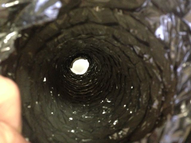
Maybe you’re thinking it’s flex duct that’s not pulled tight or not using rigid elbows or maybe even the dreaded ductopus. Those things are related, but we need to go back further. We want the root causes. This is basic physics I’m talking about. Maybe looking at the image below, a view through a piece of flaccid flex duct liner, will give you an idea of what’s to blame.
Friction
The first cause of reduced air flow is friction. When air moving through a duct rubs against the inner surfaces of that duct, it loses energy. It slows down. Its pressure drops. The more it rubs, the more those things happen. It’s like walking down a busy sidewalk with your shoulder rubbing against the buildings.
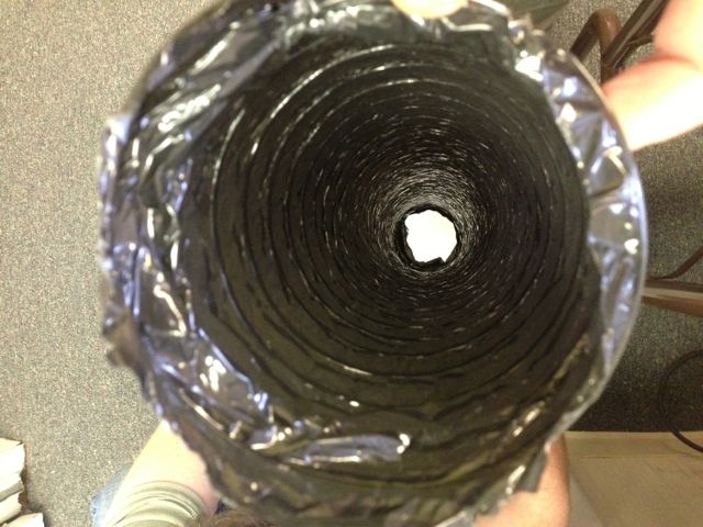
The amount of friction depends on the nature of the material the duct is made of, how it was installed, how dirty it is, and how fast the air is moving. The photo above shows flex duct that’s not pulled tight at all. Even though you can’t see it all that well, you can tell that there’s probably going to be a lot of rubbing when air moves through that duct. The same flex duct pulled tight is shown below. It still looks a bit rough but is much better than the one above. A piece of rigid metal duct would provide a much smoother surface.
Turbulence
The other primary cause of reduced air flow is turbulence. This one is a kind of friction of the air rubbing against itself. The main cause of turbulence within ducts is turning the air. When you send air through a 90° turn, the type of fitting you use to do so can make a big difference.
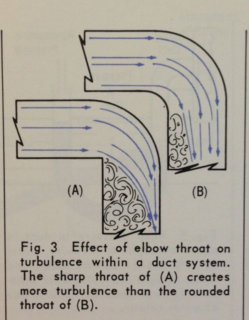
The diagram below is from ACCA’s booklet Understanding the Friction Chart. In both of the 90° elbows, the air enters nice and smoothly. That’s laminar flow. When it makes the turn, however, notice that the air in the elbow with the curved inside edge (the throat) results in less turbulence. The elbow with the square throat produces more turbulence. Pick your fittings carefully!
Friction rates and pressure drops
The result of friction and turbulence, as I said above, is that you get a drop in the pressure. As air moves through a supply duct, the pressure created by the fan behind it keeps it moving. The farther it travels down the duct, though, the more that pressure is reduced by friction and turbulence. That’s true in good duct systems as well as bad.
Both of these causes, friction and turbulence, are included in the friction rates given for various types of ducts and fittings. As the word ‘rate’ indicates, the friction rate doesn’t tell the whole story. You’ve got to combine it with something else to figure out what the whole pressure drop is. That’s where equivalent length comes in, and I’ll save that for a future article. Or you can skip ahead and go read Manual D.
When designing and installing ducts, you’ve got to know about this stuff. Friction and turbulence play a big role in whether a duct system does what it’s supposed to or not. We’ve got this stuff quantified. If you’re not using Manual D or a ductulator or some other method that quantifies these effects, you may well end up with a system that no amount of commissioning can save.
Want to dive deeper into this subject? See my series on duct design, starting with: The Basic Principles of Duct Design, Part 1
Allison A. Bailes III, PhD is a speaker, writer, building science consultant, and the founder of Energy Vanguard in Decatur, Georgia. He has a doctorate in physics and is the author of a popular book on building science. He also writes the Energy Vanguard Blog. You can follow him on Twitter at @EnergyVanguard.
Related Articles
How to Install Flex Duct Properly
Keep Your Elbow Rigid — A Lesson in Flex Duct Installation
Don’t Kill Your Air Flow with This Flex Duct Disease
NOTE: Comments are closed.
This Post Has 12 Comments
Comments are closed.
This is so common especially
This is so common especially on newer homes with slab. Which begs the question; If airflow is so bad how can you truly trust duct leakage test results??
I have designed a duct system
I have designed a duct system with an IWC PD/100 of .5 (and it will probably be installed and commissioned to a .6 or .7). I specified rigid ducts in many parts but an experienced contractor let me know; although the material cost for rigid duct and flex duct is the same, the installation costs for rigid duct are about five times higher. He suggested flex duct with a liner. Of course it still needs to be pulled at a (I forget the lbs pressure for pull and count of time demanded by Manual D right now) certain pressure for an amount of time before installation, and have no more than 4% sag on straight runs, but he said that his brand of flex duct had the same pressure drop rate or close to the same as the IWC PD/ 100 ft. that rigid duct exhibits. This is great, and he said it costs not much more in material. Is anyone else familiar with this “duct liner inside of flex duct”?
Most HVAC guys wouldn’t know
Most HVAC guys wouldn’t know what a turning vanes is or what it’s function is if it hit them in the face. Ha…
Although I am in no way an
Although I am in no way an airflow expert, I did spend several years trying to troubleshoot a too-cold bedroom. In the process I bought Manual D (and Manual J) and did a lot of online talk with HVAC professionals.
Sizing. That is what I submit must be added to the list of causes of poor airflow. Return ducts are often under sized for the airflow required, and people often fail to recognize flex ducts need to be sized larger than hard duct for a given air flow. Filters are often installed with really high face velocities, making them both more restrictive when clean, and more vulnerable to air flow problems when in service a few months.
At the same time the industry is notorious for OVER sizing the AC equipment. Maybe heating too, but where I live AC dominates. For existing homes, this leads to an opportunity when replacing equipment: Choose smaller equipment, and the reduced air flow is more forgiving of the capabilities of the duct and filter system. Or add a new return to increase filter area and air flow capacity.
Of course it is superior to design right in the first place, which is a situation which only applies to new construction. Many more of us are left to clean up the problems created by poor decisions during that original construction.
It would be most effective if
It would be most effective if you politely asked the outside consultant for the performance curve of the blower he is specifying. The operation of a centrifugal blower motor is the highest operating cost in most comfort systems, annually trumping the operation cost of a refrigerant compressor, outdoor axial fan, or geothermal closed loop water circulation pump.
Centrifugal E.C.M. blower motors commonly installed in residential systems operate at their most energy efficient against an IWC PD/ 100 ft. of equivalent duct length of .4 to .6. Many persons employed in the residential market are not aware and design–or just install–comfort duct systems to an IWC PD of 1.0 or even 2.0.
Also, if you design a residential system to exactly .8 IWC PD, the ducts will most likely, finally be installed to perhaps 1.0 anyhow.
For residential buildings in California one particular code is becoming more stringent and will only allow a maximum of 300 fpm in return ducts or return duct registers (yes, that makes for one ginormous amount of return register, AK, or free area). This requirement solves many problems inherent to duct design and installation when performed by many residential installers; it lessens noise pollution, collects more particles due to a slower rate of flow at a filter, and ‘hopefully’ cuts down on the power draw of the blower motor.
That code does not mention turbulence mitigation or equivalent duct diameters before, or after, the blower, but I think this is an error on the code writers’ part.
A comfort system performance issue resulting from duct and duct register design and specification that many fail to pay attention to is the direction or characteristics of air-throw (an endearing term I use instead of “airflow”) from supply registers to indoor comfort zones. Proper indoor air-throw can be specified prior to construction by first determining air duct velocity just before any supply register and de-rating that velocity for any turbulence created by the upstream ducts or general system effect, then looking up the performance data from a good air supply register manufacturer and noting the tested and documented air-throw length, fall, or fpm. Good manufacturers will also note the temperature or temperature differences used in their labs during the determination of performance documentation. This is all explained extremely well in ACCA’s Manual T.
A lot of methods for duct system design employ safety factors or result in unbalanced systems before on site balancing. One of the most effective ways to install comfortable indoor airflow to and from occupants is to test velocity at the end of ducts, after duct installation, and before register specification or register installation. In my opinion this should be a step involved during nearly every system installation’s commissioning, testing, and permanent balancing stage.
(If you are not in a home from the 70’s and have no jumper ducts, close a door if you want to make testing, balancing, math, and real world application more chunky.)
For variable speed blower operation there is a method in Manual D section 9-15 that can be employed to kinda ‘fudge’ a compromise regarding air-throw, comfort, and noise when installing single speed supply registers (to do this you need to locate or determine through engineering assumptions the previously mentioned register performance data). But I think that testing and balancing on site is more effective than most any specification of supply registers without it.
In your commercial industry you have an advantage because almost all systems are designed by engineers and almost all equipment performance is properly documented; circumstances are often opposite in the residential industry. I have not yet designed a commercial system, but the mathematics in regards to operation of blowers against the resistance of finally installed duct systems never change.
Again regarding your first question0 about duct design and code or best practices, your IWC PD should be specified while paying attention to variables such as noise, the material cost to the client to upsize ducts, the expanse that you have where all of those ducts are installed, and final balanced air throw at all installed registers just to name a few. But an important variable that I was not aware of until taking classes form experienced service providers is the “sweet spot” in the curve of the blowers commonly being installed in new systems, and, although E.C.M.s motors are forgiving, the resultant operation cost and eventual, higher maintenance cost incurred when we do not specify and operate comfort system centrifugal blower motors within this beneficial parameter. “We should first sell comfort to a client” and then work our way backwards, but we must also keep in mind the operating costs that a client will pay for many, many years after our design and installation.
Regards,
Conor
P.S. Does anyone have experience with an entirely flex duct system WITH A LINER INSIDE while say installing to a tested, after commissioning and balancing, IWC PD/100 (may include airflow through house); noting manufacturer documented blower kW; and recording performance, by recording kW at the proper blower speed, against that tested IWC PD/ 100–with that lined flex duct?
Agree with need but it is
Agree with need but it is almost impossible and rare in houses over 40 years old and those with small crawl spaces.
CONOR — You reported “.
CONOR — You reported “…Centrifugal E.C.M. blower motors commonly installed in residential systems operate at their most energy efficient against an IWC PD/ 100 ft. of equivalent duct length of .4 to .6…”
I may not be understanding exactly what the definition of efficiency is here. Perhaps you can help break it down into simpler terms.
My furnace is American Standard ECM type (model AUD080R9V4K) and I was fortunate enough to snag a copy of the Service Facts document. It compares wattage vs ESP, External Static Pressure measured in IWC, inches of water column. From it, one measure of efficiency:
Nominal 1200 cfm air flow,
1) at 0.1 ESP, 170W, rated air flow 1163 cfm
2) at 0.3 ESP, 230W, 1178 cfm
3) at 0.5 ESP, 285W, 1188 cfm
4) at 0.7 ESP, 345W, 1183 cfm
5) at 0.9 ESP, 405W, 1178 cfm
First of all, am I speaking the same vocabulary as you? Second it would seem energy efficiency goes down as ESP goes up — which argues against the existence of a sweet spot if I understand what you say.
Again, to CONOR: You reported
.
Again, to CONOR: You reported “… The operation of a centrifugal blower motor is the highest operating cost in most comfort systems, annually trumping the operation cost of a refrigerant compressor, outdoor axial fan, or geothermal closed loop water circulation pump.”
Hmmm. As I said in an earlier post, the ECM air handler draws in the ballpark of 300W. The 3.0 ton AC (Trane 2TTX9036A1)that makes it blow, draws in the ballpark of 2800W. What must happen for the 300W item to use more energy than the 2800W item? They generally run at the same time — no “fan on” thermostat setting for this house.
Although I live in the hot-humid Houston area, you might say I’m from Missouri
@Conor, while its true that
@Conor, while its true that blower power represents a large portion of total system power as source equipment efficiencies rise (especially for PSC blowers), as MJ said, it’s ludicrous to think that the blower will consume more power than the compressor.
Regarding 300 FPM return duct limit in CA… are you sure that’s not for grille face velocity?
Manual D specifies 300 FPM max face velocity for filter grilles. I typically specify 250 or less in high performance homes when using filter grilles.
Regarding duct liner for flex… pls post a link. I don’t have any idea what you’re referring to.
A few clarifications: 1) All
A few clarifications: 1) All flex duct comes with an inner liner, it will not make a flex duct have the same pressure drop as a metal duct of the same size.
2)Anytime you make a change of direction with a flex duct, a metal elbow is strongly advised.
3)All this talk about a friction rate to design to makes me real nervous. Remember the friction rate is set by the available static pressure after all the non-duct elements pressure drops are subtracted. Then the available pressure is divided by the total effective length.
4)With a PSC motor increasing the static pressure will slow the flow and reduce the fan motor watt draw. However it will also reduce the sensible cooling and the compressor will run longer. See http://www.proctoreng.com/utilities/Airflow.html
5)with a Brushless Permanent Magnet Motor (aka BPM/ECM) reducing the static pressure will allow the motor to provide the same airflow and sensible capacity with less watt draw.
Bill, does the rooftop unit
Bill, does the rooftop unit have a BPM/ECM fan motor or a PSC?
We bought a 3 bedroom model
We bought a 3 bedroom model condo recently (built around 2011)
I noticed that the smaller air registers (2 smaller bedrooms) and two registers in the kitchen and dining nook were not getting air flow or little air flow (tested with fan on only).
The AC company sent a tech to investigate. The tech immediately brought a a pair of tin pliers (used to bend sheet metal). He immediately bent the ar register diffusers from 45 degrees to 90 degrees (vertical).
This increased the air flow, but now the air flow only flows directly down instead of directing the air across the room.
I think that ductwork was improperly sizes or installed causing an increase of friction to the point the registers have little air flow.
I would appreciate comments concerning my thoughts on this