What Happens to Air Flow in Ducts When Size Changes?

As we continue our study of indoor air quality and filtration, we now come back to duct design. Today’s lesson is on an interesting bit of physics that applies to anything that flows. It could be heat or particles or electromagnetic energy. In our case, it’s air, a fluid, and the physics we’re looking at is called the continuity equation. It’s basically a conservation law, similar to conservation of energy, and I’ll use diagrams to tell the story.
The basic continuity
First, we have a duct. Air enters the duct from the left. As the air moves through the duct, it encounters a reducer and then a smaller duct.

What do we know about the flow here? Thinking about conservation laws, we can safely assume that every bit of air that enters the duct on the left has to come out of the duct somewhere. We’ll take the case of the perfectly-sealed duct so no air leaks out along the way.
But we can strengthen our statement from just the amount of air to the rate of flow. Using “those annoying imperial units,” we can say that for each cubic foot per minute (cfm) of air entering the duct on the left, a matching cfm of air leaves the duct on the right. We represent flow here by the symbol q.
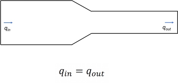
So, we have conservation of air — no air is created or destroyed in the duct — and we have conservation of the flow rate. The rate of flow entering equals the rate of flow leaving. But to make this second claim we’ve had to make an assumption.
We know the number of air molecules has to be the same no matter what, but to say the volume of air is the same means that the density doesn’t change. We’re assuming that air is incompressible when we say that. Is it true? Can we legitimately say air is an incompressible fluid?
The general answer to the question of incompressibility, as you know, is that air is certainly a compressible fluid. But we can treat it as incompressible in duct systems because the pressure changes it goes through are small enough the density of the air doesn’t change.
And that’s why our statement above, that the flow rate (in cubic feet per minute) of air entering the duct is equal to the flow rate of air leaving the duct. We have continuity!
But what happens to the velocity?
Air velocity in ducts is a really critical factor in how well ducts do their job of efficiently and quietly moving the right amount of air from one place to another. We’ll explore that topic further in a future article but for now, let’s nail down what happens to the velocity as air goes from a larger to a smaller duct.
First, going back to our statement about equal flow rates, let’s look at equal volumes of air moving through the duct system. Let’s say the narrow blue strip in the larger duct represents one cubic foot of air. I’ve shown the cross section of the duct, A1, below that strip.
In the smaller duct, that same cubic foot of air is spread out over a greater length because the cross section, A2, is smaller. Makes sense, right? You get equal volumes because the volume in each case is the cross-sectional area times the length.

The next step is understanding what those different lengths mean for the velocity. According to our equation for the flow rates, qin = qout, in the same time that whole narrow plug of air on the left will move forward by one length, the wider plug of air on the right will also move forward by one length.

Like this.

The red arrow shows the initial distance between the two plugs of air. As you can see, the distance between increased.
In the next time block, the narrow plug advances one more of its lengths. The fat plug likewise moves forward by one of its lengths.

And then again.

Each time the air advances by one cubic foot, the air in the smaller duct moves farther than the air in the larger duct. In other words, the velocity in the smaller duct is higher than that in the larger duct. And it’s related to the cross-sectional area.

That equation for area and velocity is called the continuity equation for incompressible fluids.
Steven Doggett, PhD, LEED AP, ran a computational fluid dynamics (CFD) simulation using the geometry of my diagrams above and came up with some nice images of the velocity field. Here’s the first one, simulated for laminar flow:
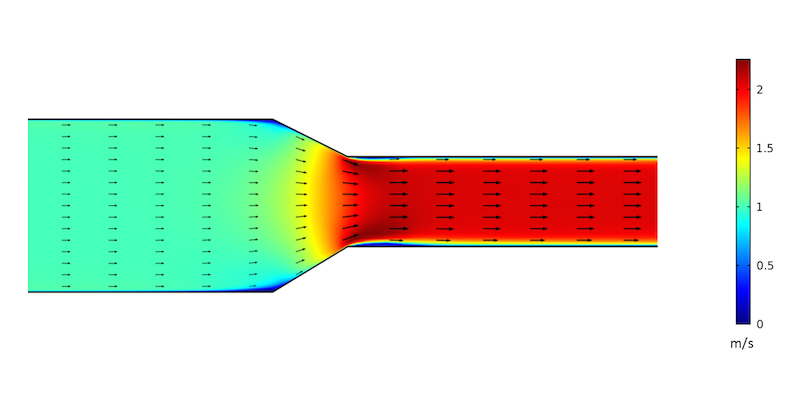
It’s interesting to see how the velocity changes in the reducer fitting. One thing to note is that this simulation assumed laminar flow whereas in real ducts there would be some turbulence. And because you’re now wondering, here is his simulation of the same thing, with turbulence:
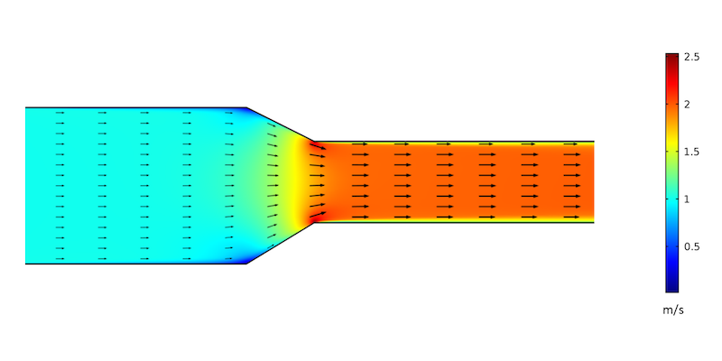
A little bit slower. A little more action at the corners. A little flatter at the reduction. Overall, pretty similar and both really interesting to look at.
The key takeaway here is that air moves from a larger to a smaller duct, the velocity increases. When it moves from a smaller to a larger duct, the velocity decreases. In both cases, the flow rate — the amount of air moving through the duct, in cubic feet per minute — stays the same.
Applications of the continuity equation
Since we’ve just looked at problems with filtering the air in my last article, you may suspect that this has some relation. And you’re right. A lot of filters cause problems with air flow because of excessive pressure drop. To solve the problem, you have to understand the relation between filter area, face velocity, and pressure drop. The continuity equation is involved. I’ll be going deeper into this with a couple of articles coming out soon.
The continuity equation is also critical in keeping the velocity in the ducts where you want it. If it goes too high, you get too much pressure drop and possibly noise.
And then there’s the issue of shooting conditioned air into rooms at the proper velocity to get enough mixing of the room air. That’s similar to the filter issue where you have to look at manufacturer’s specifications for supply registers except that you’re not trying to minimize pressure drop as with filters. You’re trying to pick the right register for the amount of air flow to get the right amount of throw and spread.
The topic in my first semester of introductory physics that I enjoyed the most was hydrodynamics, the study of fluids in motion. We didn’t get into viscosity, but we did learn about Bernoulli’s equation, Venturi tubes, and fluid velocity. I had no idea at the time that I’d be using this stuff in the real world nearly four decades later.
Of course, back in 1980 I wasn’t even able to predict that I’d be a baker in St. Louis in 1984, cleaning windows in Seattle in 1986, or teaching physics at Tarpon Springs High School in Florida in 1989. As Niels Bohr may have said, “It is difficult to predict, especially the future.”
Related Articles
The Basic Principles of Duct Design, Part 1
Converting Heating and Cooling Loads to Air Flow – The Physics
The Science of Sag – Flex Duct and Air Flow
The 2 Primary Causes of Reduced Air Flow in Ducts
NOTE: Comments are moderated. Your comment will not appear below until approved.
This Post Has 24 Comments
Comments are closed.
Nice! There are sooo many
Nice! There are sooo many aspects of the laws of physics that far too many people designing and building homes simply do not understand. You do a good job of breaking down & explaining.
Thanks, Charles. I
Thanks, Charles. I appreciate that.
You state “Each time the air
You state “Each time the air advances by one cubic foot, the air in the smaller duct moves farther than the air in the smaller duct.” Shouldn’t that read “Each time the air advances by one cubic foot, the air in the smaller duct moves farther than the air in the larger duct?”
Gary, yes, you are correct.
Gary, yes, you are correct. And thanks to you, now it does read that way. Sometimes when I’m wordsmithing, I forget to go back and change parts that need to be changed.
Allison
Allison
Great explination. Will you be doing an article using the formula? Soulving for v2.
Yes indeed, Andy. That’s
Yes indeed, Andy. That’s where we’re going with this. I’ve got two articles on filters planned and eventually I’ll write about Manual T and register selection as well.
Another great article Allison
Another great article Allison. I am looking for input on supply grill pressure drop.
Years ago wood/metal grill multipliers were topical but manufacturers didn’t pick up on this.
A good looking, free flowing wall decoration shouldn’t require a translator….
Along with the diameter
Along with the diameter change there is also the change of direction, curves and corners, that will change velocity. Eddies and wakes within the line can reduce flow. One bend can be ignored, but the octopus of duct work that Dr. Bailes posts on occasion make you wonder if education is actually applied…that pesky physics.
Harry, do you mean this one?
Harry, do you mean this one?
[[{“fid”:”2461″,”view_mode”:”default”,”fields”:{“format”:”default”,”field_file_image_alt_text[und][0][value]”:”A living example of the elusive ductopus”,”field_file_image_title_text[und][0][value]”:”A living example of the elusive ductopus”},”link_text”:null,”type”:”media”,”field_deltas”:{“1”:{“format”:”default”,”field_file_image_alt_text[und][0][value]”:”A living example of the elusive ductopus”,”field_file_image_title_text[und][0][value]”:”A living example of the elusive ductopus”}},”attributes”:{“alt”:”A living example of the elusive ductopus”,”title”:”A living example of the elusive ductopus”,”height”:”375″,”width”:”500″,”class”:”media-element file-default”,”data-delta”:”1″}}]]
Or this one?
[[{“fid”:”2462″,”view_mode”:”default”,”fields”:{“format”:”default”,”field_file_image_alt_text[und][0][value]”:”A multi-tentacled attic duct monster”,”field_file_image_title_text[und][0][value]”:”A multi-tentacled attic duct monster”},”link_text”:null,”type”:”media”,”field_deltas”:{“2”:{“format”:”default”,”field_file_image_alt_text[und][0][value]”:”A multi-tentacled attic duct monster”,”field_file_image_title_text[und][0][value]”:”A multi-tentacled attic duct monster”}},”attributes”:{“alt”:”A multi-tentacled attic duct monster”,”title”:”A multi-tentacled attic duct monster”,”height”:”375″,”width”:”500″,”class”:”media-element file-default”,”data-delta”:”2″}}]]
Or some other one?
Fantastic article and
Fantastic article and important topic you’re covering here Allison. Is the secret surprise cliff hanger going to be related to the question – “What happens to the static pressure on the duct walls when the flow velocity increases?” So exciting!!
Kristof, that sounds like
Kristof, that sounds like Bernoulli’s Principle to me. I wrote about that eight years ago.
Rats to You, Daniel Bernoulli! – Understanding Air Pressure
I even made a silly little video to go with it.
https://youtu.be/ztqPfg3qCkM
Here’s a screenshot from it:
[[{“fid”:”2463″,”view_mode”:”default”,”fields”:{“format”:”default”,”field_file_image_alt_text[und][0][value]”:”Bernoulli’s principle for fluid flow”,”field_file_image_title_text[und][0][value]”:”Bernoulli’s principle for fluid flow”},”link_text”:null,”type”:”media”,”field_deltas”:{“1”:{“format”:”default”,”field_file_image_alt_text[und][0][value]”:”Bernoulli’s principle for fluid flow”,”field_file_image_title_text[und][0][value]”:”Bernoulli’s principle for fluid flow”}},”attributes”:{“alt”:”Bernoulli’s principle for fluid flow”,”title”:”Bernoulli’s principle for fluid flow”,”height”:”325″,”width”:”500″,”class”:”media-element file-default”,”data-delta”:”1″}}]]
Allison, this has been a
Allison, this has been a nightmare year regarding our hvac, ducts, and crawlspace. Our 1981 1452 sq ft home had a dry crawspace for decades. Prior owner had it built on a crawlspace and used oil furnace heating. At some point in the past 2 decades, the prior owner switched from oil furnace to electric central hvac with heat pump in the crawlspace. We bought the home after the original owner passed away as a senior. The existing York hvac system started developing leaks in 2015. We had a service tech repair and recharge. This year the system developed leaks again and lost most of the freon. The result in our crawlspace as the unit started failing was standing water for the first time for this old crawlspace. We immediately had the system overhauled to a 25 sere Lennox. But we wanted to do a home addition in the neart future and wanted to wait to do the ductwork upgrade with the addition loan as the Lennox cost us a lot upfront already. We were assured the new unit we had installed was sufficient to manage both the current sq footage up to 2000 sq ft with the home addition. But I remained alarmed that the standing water in the crawlspace wasn’t going away after the install. A normally dry crawlspace for 27 years was unusually wet. We feared mold/mildew and wood rot was setting in. We had industrial sized fan blowing air out the crawl space door in attempts to get the standing water out. The service tech simply made some adjustments to the thermostat, but honestly, I didn’t see any improvement. We were told the ducts were sweating bad…condensation from the air flow through old flex duct. We immediately had them replace the entire ductwork throughout the house. But by the time they completed the work, my husband found wet insulation and mildew. We had a home inspector come through, and he recommended to temporarily seal the crawlspace, place a temporary dehumidifier with hose to drain outside, and then once the humidity was controlled, set off a couple foggers designed for the mildew found. He shared we caught the problem in time before damaged occurred to our joists. As home owners, we never realized this could occur. Switching up to a more efficient hvac system using old ductwork was a disastrous fail. During the removal, the new service tech explained part of the problem generating the fail was the return went from a decent size opening to a tiny opening originally designed for the oil furnace. I don’t believe any one could see that until the old system was removed. In other words, the old central hvac system was strained, too, but this old house was a leaking inefficient house when we bought. We had to immediately replace all the windows and exterior doors as well as seal off an attic stairway access to get the leaks manageable. So, with each passing year as we slowly improve the R rating throughout, we are actually making a more airtight house. The home inspector shared he has seen many disastrous results as folks in NC try to improve the efficiency of older homes with modern practices. For example, The powerful 25 sere system broke our old system and generated the standing water problem. An unintended consequence to our seeking to become energy efficient. The other problem he brought up was the encapsulating disastrous results he is seeing regularly. We were told by the hvac installers to go fully encapsulated to avoid standing water. Our home inspectior shared horror stories of the homes he inspected with full encapsulation. Mold and wood rot and significant structural damage. He’s inspected so many now that he actually discourages fully encapsulating crawl spaces in the southeast because the majority of service providers don’t know what they are doing and are failing to follow the strict NC code. I’m no scientist. But with our house having a nice and dry crawlspace with open vents in the summer and closed vents in the winter for 27 years, that tells me it isn’t crawlspace venting that generates the moisture problem but the other electronic devices we place in that space that generate the problems. And apparently it’s the duct’s conditioned air and friction from that flow that is the culprit. So, with these old houses, I’m thinking it best to not encapsulate, but to follow our home inspector’s advice with what he has seen works in our specific region for homes similar to our own. We plan to replace our vapor barrier, going up the foundation walls/columns and sealing in place. And he discourages the automatic vents because they will not close during rainy periods. He further recommended installing a couple crawlspace vent fans on the damper east side of our crawlspace to turn on as needed to dry that space. So I’m researching the different alternatives that may work. I read on another blog about the need to fully encapsulate crawlspaces or go with a slab foundation for the southeast, and my husband and I totally disagree. Slab foundations do crack with soil shifts and minor quakes and are a financial nightmare to correct whereas homes on crawlspaces may be adjusted with permanent house jacks if caught on time. Further, houses with crawlspaces permit replumbing of problematic pipes. A slab foundation requires busting concrete to get to a major plumbing problem. So, if we were to build a new house, it would still be on a crawlspace for the management flexibility. But the science on how to make it all work together at the least operating cost evades us. Should older built homes go with less sere hvac replacements when the high sere (powerful) units causes moisture problems in existing crawl spaces from condensation from the flow in the ductwork?
Dai, without seeing the site
Dai, without seeing the site and the unit and ducts in question, it is hard to say anything conclusively, but the new unit is likely at the center of the problems. I am a relative amateur compared to others on this thread, but I will take a stab at this. The SEER rating refers to the efficiency of the unit, not it’s capacity. A properly sized unit will perform well at dehumidification, and an oversized unit will perform poorly. (With that said, higher SEER units are efficient at using less energy to meet temperature set points, not dehumidification criteria. Separate issue.) My hunch is that the unit installed in your crawl space is far too large for the job it is doing this year. It may have been sized for the addition, not the current load- although many installers don’t do the proper sizing calculations and it may even be oversized with the addition. As you weatherproof your home, you reduce the thermal load, so your A/C unit needs to run less to keep the temperature at the set point. However, when the A/C isn’t running, it isn’t dehumidifying. This is why oversized units generally lead to problems with humidity- especially in the Mid-Atlantic and the Southeast, where humidity is a challenge for several months of the year. Old leaky ducts and poor duct insulation also played a part- condensation would be expected with humid air against cold ducts. External influence is also involved. Did anything change with the exterior? Landscaping, rain gutters, exterior slope where the addition will attach? Anything that doesn’t shed water away from the crawl space is a problem. I don’t know about NC, but here in the DC area we got more rain last summer than in the last several decades, over 30 years. Moisture issues appeared in many buildings that never had problems before. Generally it was because these properties were just on the edge previously, and all it took was an unusual stretch of wet weather to push them over the edge. I will agree with the inspector that an improper encapsulation job isn’t the answer, but properly encapsulating AND conditioning the crawl space would make sense. Not the only answer, but current evidence indicates it is more effective than anything else when done right. Just because some people make horrible barbecue doesn’t mean barbecue is bad food.
Thank you Allison, very
Thank you Allison, very informative article. One trouble with residential forced warm air systems is house builders don’t want central heating, they hate boxing-in ductwork and rarely does anyone bother to commission a system to prove its working half decently.
All elbows are short radius, tapers are too short and return boots often have no throat at all creating unnecessary turbulence. All this in an effort to keep the system out of the way. I’m starting to like the small duct high velocity product that Unico and others have on the market. Seems to solve a lot of FWA problems. Are you familiar with SDHV?
I am shopping for a hood fan
I am shopping for a hood fan and see some great ones with 8″ diameter ducting. I also read about appropriate CFM per BTU gas stove and per foot width of electric stove and kitchen svolume. I notice my kitchen has a 4″ dia. duct and I expect that it is quite common for installations to use reducers when routing through cabinets and walls. Perhaps you could expand your article to include any effects of reducing the duct size on the effective CFM ie. velocity decrease due to duct drag. Thank you
Good day from France.
Good day from France.
Just one question :
I have two duct going to the same cooler. One is 3 inches diameter, the other one 2 inches diameter.
Air speed is the same on both inlet, so same pressure.
What happen to the speed and pressure inside both duct and does one duct take over the other one and can return some air and/or pressure in the other one if some conter pressure is done by the cooler?
Thanks for your help!
Jacques
difficult material
difficult material tocomprehend
Hi, in a short length of duct
Hi, in a short length of duct (20 meter) with 5 supply outlets for cooling air. should the outlets be sized smaller ( smaller at the plenum end) to bigger to improve and make more efficient the air flow?
Hi! Is the flow rate has a
Hi! Is the flow rate has a maximum capacity limit of air volume (cfm) it can get based on the duct size or take off ductwork?
No mention of compression
No mention of compression creating heating, in a duct. Clean compressed air, leaving a nozzle, appears not to heat up the nozzle. Duct air is not clean, wouldn’t there be heat created by the particles?
I THINK IF I RUN A 4″ ROUND
I THINK IF I RUN A 4″ ROUND PIPE ACROSS A 12 INCH DUCT, THROUGH THE CENTER IT WILL HAVE LITTLE EFFECT ON AIR FLOW. IT IS A 12 X 20 DUCT AND WOULD PASS THROUGH THE DUCT IN THE CENTER. NO TAKE OFFS ARE WITHIN 5′ OF WHERE THE 4″ GOES THROUGH
Hi,I have an issue with my
Hi,I have an issue with my airflow in my master bedroom only (other rooms are fine) where I have two registers, I can not tell if it’s a too much cold air flow or if it’s too fast air flow that is making my room uncomfortable( too cold too fast) while Maintaining a good balance with the other rooms in the summer time and waking up sick every morning, Any suggestions please? thank you in advance
I’m glad I found your blog
I’m glad I found your blog because it seems to provide the knowledge I need to solve this little puzzle I have when designing a window outlet for my mobile a/c. But as I read through some of the posts, I also realize that there are many more variables to consider than I originally thought of so that I suspect: even if I managed to learn everything you explain here, I may still not be able to base my design on it because I would have to make a number of assumptions to reach a sufficient level of simplicity and making those assumptions wold require further knowledge. So, I decided to post a comment here and ask you for some pointers that might allow me to focus on the most relevant variables.
So here is the puzzle:
I have one of those mobile a/c units that come with one exhaust duct that you’re supposed to hang out the window or so. For reasons that I don’t need to explain to you, I modified the unit so that I now have two ducts hanging out the window: one sucking in outside air and one blowing it out again about 20 degrees C warmer. So far so good.
I have now designed and 3D-printed a fitting that allows me to close the window to such an extent that almost no outside air comes into the room. The basic principle is to transform the round cross section of the duct into a slim rectangular one while maintaining the area of the cross-section because my intuition told me that reducing the duct size will make my a/c less efficient (and ultimately perhaps even damage it).
So the basic puzzle is this: in order to close the window as far as possible, I need to minimize the size of the rectangular end of the fitting while not making it too small and the question is: how small can I make it?
From the above blog post, I now understand that what I’m trying to do is minimize the pressure drop of my exhaust fitting.
The first version of my design is based on the following reasoning: Although the outside diameter of the duct is 150 mm, the inside is only about 135 mm because of its accordion-type design. So the area of the cross-section is 143 cm2. The with of the rectangular end can be max 36 cm long so that it needs to be about 4 cm high in order to maintain the same area.
I have obviously ignored that the walls of the accordion duct have quite some resistance while the walls of my 3D-printed part are nice and smooth. So there might be some room for further reducing the height of the rectangle, but if I start considering turbulence, I would also have to consider that my exhaust forces the air to change direction at a 90 degrees angle and I have no idea how that weighs against the resistance of the accordion walls. Probably the walls are a lot worse.
But here’s the thing: even if I were able to calculate (or measure) the exact pressure drop of my fitting, what does it mean? I’m starting to suspect that my consumer grade mobile a/c doesn’t really care about the extra pressure drop of my exhaust, given that the designers didn’t consider the accordion walls a problem. But even if it tolerates a lot, it will definitely become less efficient, so I’m nonetheless curious to try and optimize my design. So what’s most important and ho do I know whether I can reduce the size of the exhaust?
Two adjacent shops with
Two adjacent shops with separating wall. Left is 24 x 30 with 8640 cf including open ceiling. Other is 10 x 30 with 2250 cf including ceiling. Smaller room has 3000 cfm exhaust fan at back wall. Question: If I install a opening at the back of the larger room, in the connecting wall, and within 4 ft of that exhaust fan, will that 3000 cfm rated fan clear any fumes from the larger room? What size wall opening would be sufficient? This is an attempt to save not adding another exhaust fan and hole to the outside. I do know that exhaust fan is capable of handling twice the volume I have stated….thanks…mike