The Secret to Moving Air Efficiently through Your Duct System

At my first Building Science Summer Camp in 2011, David Hill (in the photo below) gave a great presentation on some of the big problems with duct systems. (In case you weren’t reading this blog back then, I got myself invited with my 2010 article called I Don’t Need No Stinkin’ Building Science Summer Camp.) Michael Chandler ably summarized that talk in his article, Stuff I Learned at Joe Lstiburek’s House, Part 2. This year, Hill did a followup presentation, reprising some of his main points but also adding two new pieces, one of which is a nice study he’s been involved with on air flow in oval ducts.
Furnaces are getting smaller
In the first half of Hill’s presentation, he reminded us about some of the fundamentals of air flow in ducts that he covered in 2011. But he did throw out one new thing there: He said that manufacturers, in their drive to improve efficiency of their equipment, are making furnace cabinets smaller while at the same time increasing air flow. Then there’s the absence of integrated design in new construction, leaving HVAC designers and installers not nearly enough room to do their jobs well, so duct systems are smaller, too. The combined effects, Hill said, make furnaces like “a pinhole with a hurricane going through it.”
Air flow, friction rates, and equivalent length
As mentioned above, Michael Chandler did a good job summarizing Hill’s 2011 presentation, so I won’t do much more with his reprise of that here. I do want to say a few things, though, because air flow is so important and so often misunderstood.
One thing certainly bears repeating from Hill’s presentations, though, is that air flow can be reduced two ways. The first is friction, or air resistance. The second is turbulence. Friction happens throughout. Turbulence happens mainly when you turn the air in the duct system, and that happens at fittings. As you might expect, it’s the fittings that reduce air flow the most.
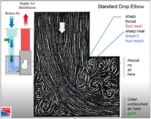
HVAC designers often use something called a ductulator to determine the sizing of the ducts they use, but it’s easy to misuse them, too. Ductulators tell you how much pressure drop you’ll get in a 100 foot run of straight duct of a certain type. They don’t tell you what happens when you get turbulence at the fittings.
That’s where this thing called equivalent length comes in. Each type of fitting is assigned an equivalent length, which is the length of straight duct of the same type and size that would give you an equivalent amount of friction (or pressure drop). So what you do is figure out the total equivalent length of your most restrictive run in a duct system and design for that pressure drop.
When is an oval not round?
Oval ducts are used sometimes because they fit inside wall cavities. Because they have the rounded corners instead of square, a lot of installers assume oval ducts are equivalent to round duct. If you look at the photo below, you’ll notice that the oval duct is really just a round duct that’s been flattened out. It’s even stamped with the same number – 6” – even though the dimensions are different.
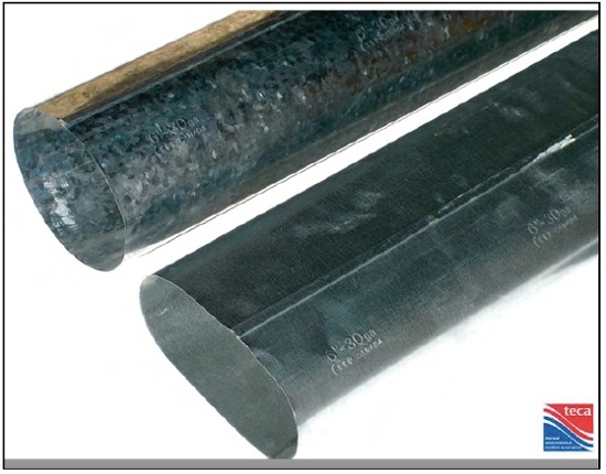
It turns out the air flow properties are different, too, although they haven’t been studied much. Hill and his colleagues undertook a research project to find the equivalent lengths of some common oval fittings, and he showed the numbers in his presentation.
If you download Hill’s presentation and scroll down to page 15, you can see what they found. One thing they found is that the straight duct itself moves less air than the same size round duct. They compared a 6” round duct to two forms of oval duct made from a 6” round: 3” x 7.71” and 3.25” x 7.57”. Their measurements showed that those two sizes of oval duct are equivalent to round duct at 5.02” and 5.18”, respectively. (See page 20.)
Just because a 6″ oval comes from the same piece of metal as a 6″ round doesn’t mean they have the same cross-sectional areas. They don’t, so you would expect them to move air differently. If you need to move the same air as in a 5″ round, you’ve got to use a 6″ oval. For a 6″ round, you need an 8″ oval.
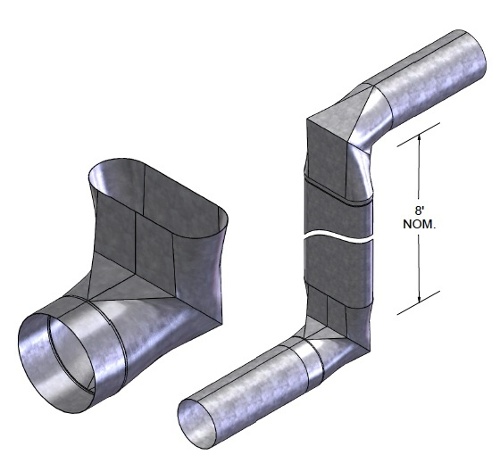
It’s the study of fittings, though, that’s most important because that’s where most of the air flow gets lost. In their oval duct and fitting study, Hill and his colleagues looked at 16 different configurations. The one shown below is number 6 in their chart. It’s a round-to-oval 90° elbow, and it has equivalent length of 29′, 55′, or 110′, depending on the sizes of the round and oval sections. You get the lower numbers when the oval side is bigger than the round side.
When you go from 6″ round to 6″ oval, you get 110′ of equivalent length. Wow! That means that a fitting that is somewhere around 1′ in actual length reduces the air flow as much as 110′ of straight 6″ duct.
In the end, they put together a nice chart and table of the equivalent lengths of various oval fittings. (See below for download links.) As you can see in the table below, one of them is a real pig, coming in with an equivalent length of 149’. That’s the transition piece from 5” round to 5” oval. If you want 6” oval, you really should go with 5” round because that has an equivalent length of only 24’. If you need the 6” round on one end, take the oval up to 8” and your equivalent length is 60’. In short, the oval side needs to be bigger than the round side.
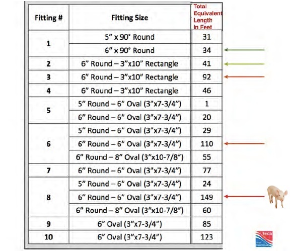
This was great work by Hill and the group he worked with on the oval duct study. Air flow is a huge problem with a huge number of forced air systems, so the more we can hear about how to do it right, the better. No matter what kind of ducts you use, the secret to moving air efficiently through a duct system is to pay attention to how you turn the air and what fittings you use. Yes, you’ve got to get the sizes of the straight runs correct, but how you turn the air makes a much bigger difference in the results. Flex duct can work well, too. Just don’t try to turn the air with it (unless it’s a long, gradual turn with the inner liner pulled tight).
The alternative is just to throw something together when you get to the job site, and then you end up with stuff like my new favorite duct disaster.
Downloads
David Hill sent me the following two documents so you can have a copy of the summary and chart and also a 7-page writeup of the study. In the longer writeup you’ll also find information about how they use another metric besides equivalent length: the number of fittings.
Oval Fittings Summary & Chart (pdf)
Related Articles
The 2 Primary Causes of Reduced Air Flow in Ducts
The Sucking and the Blowing — A Lesson in Duct Leakage
NOTE: Comments are moderated. Your comment will not appear below until approved.
This Post Has 7 Comments
Comments are closed.

Ouch!
Nice work Allison.
Ouch!
Nice work Allison.
Nice article.
Nice article.
It is a pleasure to be able to access this content outside of the Green Building Advi$or paywall.
Excellent summary of David’s
Excellent summary of David’s excellent presentation at summer camp. Meeting him was a highlight of my time in Westford this year. I now see clearly why he was wanting to know more about how poor airflow affected the vapor compression refrigeration cycle (hence my sketch of the cycle, the photo of which you tweeted), and while he told me he greatly appreciated my input, the feeling is mutual when I saw his presentation. The study he and his colleagues conducted on pressure drop through duct fittings is eye opening, and will give me good material for when I teach residential duct design this fall semester.
Therefore, thank you for continuing to spread the word about why good duct design is so vital to system performance and human comfort, and thanks also to our friend David for sharing his knowledge in this effort.
It’s interesting to see the
It’s interesting to see the results of this experiment. WRIGHTSOFT list the standard round to oval 90 degree boot to have an equivalent length of only 30′. Reading this, that value varies depending on the sizes being used. How can we properly design air system when given different information?
To get an immediate
To get an immediate comprehension regarding the loss of capacity with oval ducts (including constricting/ ovaling metal & flexible ducts) : take a styrofoam cup and fill it with water to the top. Next, oval the top. It becomes apparent that the cups capacity changes- just like an oval air duct.
Allison, you continue to
Allison, you continue to amaze me with your copious blogs and such down to earth informative information. I appreciate your continued support of building science and the HVAC-R industry. Students of the process so often overlook the importance of the building the systems are placed in (load design), much less the “side job” of installing the ductwork. As processes like BIM move into and grow with residential projects we will all benefit. I am still trying to figure out how the architect/designer/builder expects us to move “16” of return air through inadequate space, often at right angles, changes in plain, and spaces not designed to accommodate airflow.
Thanks, Keith. I amaze myself
Thanks, Keith. I amaze myself, too. In fact, I’m not sure I really do all this. I guess it helps that I outsource all of the research and writing to the Phillipines.
Regarding how down-to-Earth my stuff is, I’m reminded of what Isaac Newton said:
“If I have seen further, it is by standing on the shoulders of giants.”
My version of that would be:
“If I have been more down-to-Earth, it is by being squashed into it by the boots of giants.”