What’s the Correct Air Flow for an Air Conditioner?

Air conditioning is a wonderful thing. Now that warm weather is returning here in the northern hemisphere, ACs are getting turned on and cranked up again. The air in a house gets warm because of the heat coming in through the building enclosure and also the internal gains (lights, appliances, occupants…). An air conditioner works by passing that air over a cold coil. But for it to work properly, an air conditioner needs the correct air flow.
But let me point out right upfront that comfort depends on more than the temperature of the air. The temperatures of all the materials in the room actually matter more than air temperature. Those temperatures average out to what’s called the mean radiant temperature. (See my article on naked people and building science.)
Why does air flow matter?
Air is a low density fluid. It can gain or lose heat through contact with nearby materials that are at different temperatures than the air. Heat flows from warm to cool, you know. Let’s say you’ve got the air in the house nice and cool. Then the sun heats up the roof, which heats up the attic, which eventually heats up the ceiling drywall. The cooler air in contact with the warmer ceiling absorbs heat and increases in temperature.
The air conditioner continually recirculates air in the house to grab those BTUs picked up by the air and send them back outdoors. How does it do that? By passing the indoor air over a bunch of metal plates that are much colder than the air. And that’s where things get tricky.

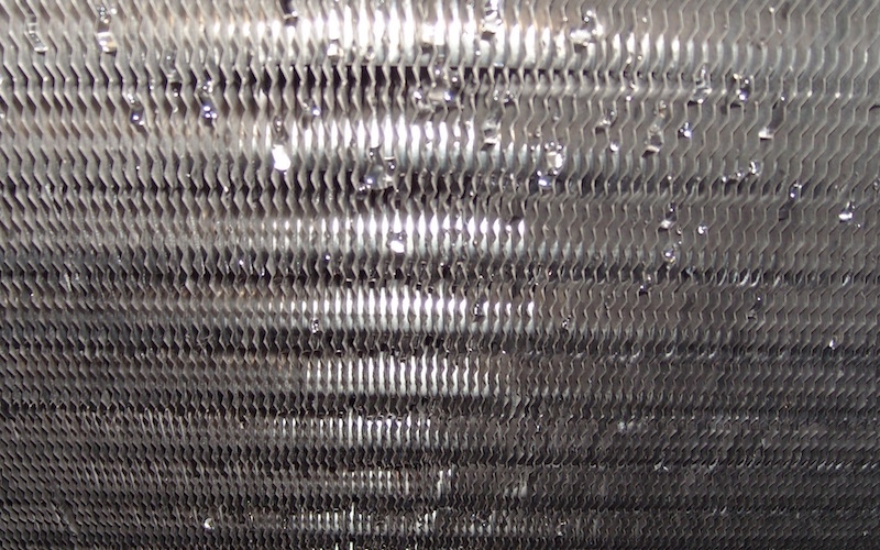
The plates are actually aluminum fins with embedded copper tubing, and the whole thing is called the evaporator coil. It gets cold because of very cold refrigerant flowing through the copper tube. (See my article on the magic of cold.) So we have two separate flows here: the air passing across the coil and the refrigerant flowing through it.
What climate are you in?
The first thing to know here is that the velocity of the air matters. When the air moves quickly through the coil, it cools down to a certain point. If you now slow that air down so that each little bit of it spends more time in contact with the coil, it gets cooler. And that leads us to this conclusion:
Slower air means colder air.
But that’s not all. An conditioner isn’t just an air cooler. It also removes water vapor from the air stream. And as the velocity of the air drops, more of that water vapor will hit the below-dew-point coil and condense. So the other big conclusion here is that:
Slower air means drier air.
And we can put those two things together to make an important statement about air flow velocity and climate:
Humid climates need slower air; dry climates need faster air.
Maybe you’re wondering now how slow or how fast should it be? I’m glad you asked.
An important metric
For best air conditioner performance, we need to match the flows of air and refrigerant mentioned above. And for that, we have a special metric that’s a ratio of the air flow rate in cubic feet per minute (cfm) to the air conditioning capacity in tons (1 ton = 12,000 BTU per hour). When you hear someone talking about cfm per ton, they’re talking about homing in on the correct air flow.
Now, the air velocity relates to that special ratio of cfm/ton, too. When the air moves at a lower velocity (feet per minute, fpm), it also has a lower air flow rate (cubic feet per minute, cfm). So by slowing the air down, the cfm/ton goes down, too. (Let’s ignore for now that changing the air flow changes the AC capacity.)
With that metric, we now can lay out some ranges of air flow targets.
- 300 to 350 cfm/ton – humid climates
- 400 cfm/ton – “nominal” air flow
- 450 to 550 cfm/ton – dry climates
Those numbers aren’t hard and fast, however. They’re simply guides that you use when selecting the correct air flow for an air conditioner. And that brings us to the next section.
Cooling loads and the correct air flow
Matching the correct air flow with the refrigerant flow tells what the cfm/ton is. But the refrigerant flow part of this exercise depends on the cooling loads in the house. Cooling loads are divided into two components. The sensible cooling load is the amount of cooling we need to lower the temperature of the air. And the latent cooling load tells us how much latent heat we need to remove through the dehumidification that happens when water vapor condenses on the coil.
Ed Janowiak, the HVAC design education manager for the Air Conditioning Contractors of America (ACCA), recently did a little “Hey Ed” video in which he said:
The correct airflow for an air conditioner will be one that meets the sensible, meets the latent, and doesn’t exceed the total by 15, 20, or 30 percent, depending on the compressor technology.
So we need to have enough air conditioning capacity to lower the temperature and remove humidity. But we don’t want to exceed that just-right capacity by too much because that can cause problems. The 15, 20, or 30 percent numbers Ed threw out there relate to whether the AC is of the fixed capacity, multi-stage, or variable capacity type.

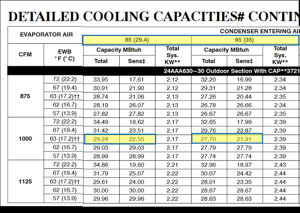
The actual process of making that selection requires diving into the manufacturer’s performance data for the air conditioner you want to use. The screenshot above shows what that looks like. If you know how to read that table above, you can see that the AC capacity depends on the outdoor air temperature, the indoor air temperature, the indoor humidity, and the air flow rate.
Example of air flow ratios
I’m not going to explain the whole Manual S process of using those data to select the proper equipment, but let’s do a little example here. The table above shows total and sensible capacities for two different temperatures (85 and 95 °F). If we do the 85 °F calculation first, we divide the air flow rate by the total capacity in thousands of BTU per hour (kBTU/hr). But first, we want to change units so we end up with cfm per ton.
29.24 kBTU/hr x (1,000 BTU/hr / kBTU/hr) x (1 ton / 12,000 BTU/hr) = 2.44 tons
1,000 cfm ÷ 2.44 tons = 410 cfm/ton
OK, that’s close to our nominal air flow rate of 400 cfm/ton. If we want to use this air conditioner in a humid climate, we’d choose the lower air flow rate of 875 cfm. Also, I’m choosing the row for the EWB (entering wet bulb, a humidity metric) of 63 °F.
28.74 kBTU/hr x (1,000 BTU/hr / kBTU/hr) x (1 ton / 12,000 BTU/hr) = 2.40 tons
875 cfm ÷ 2.44 tons = 365 cfm/ton
I’ll leave the dry climate calculation (1,125 cfm) for the 85 °F outdoor temperature to you if you’d like to try it. The answer you’re looking for is 456 cfm/ton.
Be aware that when you change the air flow rate, you also get a different cooling capacity. You still have to be in the Manual S ranges for sensible, latent, and total capacities. It’s a juggling act.
Airing it out
I’ve just scratched the surface of this topic here. And as you can tell, it’s a tricky subject. But doing it right in the HVAC design process doesn’t ensure you’ll have the correct air flow. How the unit is set up by the installer can make a difference. And how well the ducts move the air can affect it, too. In general, following these steps will get you the air flow you need:
- Start with a heating and cooling load calculation and then go through the full HVAC design protocols.
- Install the system properly.
- Commission the system and make any adjustments necessary.
I’m a big advocate for third party HVAC design. Of course, I may be biased because that’s the biggest part of what Energy Vanguard does. If you don’t hire a third party, find a contractor who will do those steps for you. There are some good ones out there.
When you have a cooling system that’s designed, installed, and commissioned properly, the air flow will be correct. And you should hardly notice the system when it’s on. Good HVAC design is 99% invisible.
Allison A. Bailes III, PhD is a speaker, writer, building science consultant, and the founder of Energy Vanguard in Decatur, Georgia. He has a doctorate in physics and is the author of a bestselling book on building science. He also writes the Energy Vanguard Blog. For more updates, you can subscribe to Energy Vanguard’s weekly newsletter and follow him on LinkedIn.
Related Articles
Converting Heating and Cooling Loads to Air Flow – The Physics
The Science of Sag – Flex Duct and Air Flow
The Best Velocity for Moving Air Through Ducts
Comments are welcome and moderated. Your comment will appear below after approval.

Allison: You are a third-party system designer and advocate for that service. Do you also do commissioning? If I were having another house built, I would like to have some verify things such as duct tightness, envelope tightness, proper airflows and duct static pressure, etc. after it is built.
Roy: We’ve done a little commissioning in the Atlanta area but haven’t done much. There are people in a lot of the metro areas in North America who can do it, and we may start doing more some day. We’ve certainly talked about it.
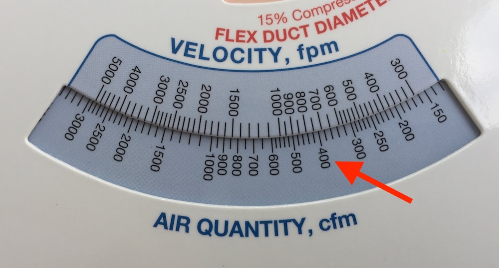
where did you get a velocity to cfm slide ruler as shown inyour artical ?
Thomas: Sorry, I should have mentioned that. It’s a snippet from a photo of the ASHRAE duct calculator. Here’s the page for it in the ASHRAE online store:
https://store.accuristech.com/ashrae/standards/duct-size-calculator-i-p-si?product_id=1935218
Good point, indoor relative humidity also depends upon the temperature of the room. If you like a cooler room temperature, the lower the temperature leaving the cool needs to be. Most cooling load outputs will give you the space sensible heat ratio, you use that to establish a target leaving coil temperature with a psychrometric chart. Also the old rule of thumb 400/cfm per ton was based on a lot more sensible heat load on a space, modern appliances such as LED light fixtures, energy efficient refrigerators, induction cooktops, LED tv’s, etc. have reduced the sensible loads, not to mention more efficient building envelopes.
Thanks for the article.
“Good HVAC design is 99% invisible.” I like that line. Best for mental health if its not apparent to the occupant that a building is being heated or cooled.
I’ve always said that comfort is the absence of discomfort.
Imagine how much easier life would be for the compressor and the evaporator if it were water cooled and not air cooled?! By introducing capacitance into the system air flow rates and refrigerant flow rates etc. can be decoupled. 😉
I’m commenting here on your blog at https://www.energyvanguard.com/blog/path-low-pressure-drop-across-high-merv-filter , because comments on that blog are closed.
It seems to me that when you relate filter area and air velocity to pressure drop, that’s meaningless unless you measure the actual filter area, not the cross-sectional area of the filter. I would expect the pressure drop across a 4″ thick 20″x20″ filter to be roughly one-fourth that across a 1″ thick 20×20 filter. But then again, maybe not, because the air going thru that 4″ thick filter is at the same pressure, and maybe crossing the filter at the same air velocity? Do we measure velocity along the vector perpendicular to the filter surface, or in the direction the air is moving? What direction IS the air moving when it goes thru a heavily pleated filter?
I’d really like to know the answers, because if a 4″ thick give the same pressure drop as a 1″ thick with the same cross-sectional area, then I can save a lot of money on filters. My expectation is that the 4″ thick will have somewhere between 1/1 and 1/4 as much pressure drop. But that range is so high that any talk about numbers without knowing that is pointless.
Phil: For more filter area to correlate to lower pressure drop is the logical assumption. At least in one study, though, that’s not always the case. I wrote about this and other research on air flow and pressure drop in a 2019 article:
Do High-MERV Filters Always Reduce Air Flow?
https://www.energyvanguard.com/blog/do-high-merv-filters-always-reduce-air-flow
About study #2, I wrote:
“The final result I’ll mention here is that they didn’t see as much difference as they expected for filters of different depths. For example, ‘the 4-inch Filtrete 1550 (MERV 12) was only marginally better than the 1-inch Filtrete 1700 (also MERV 12) and the two other [1-inch] MERV 11 filters of the same brand (1000 and 1085).'”
Thank you! I suspect that what’s happening is that the bottleneck in the case of highly-pleated 4″ filters isn’t pushing air thru the large filter surface, but pushing air into the wedge-shaped “waiting area”, if you know what I mean. So when the static pressure drop across your 4″ filter appears to be .06 iwc, that isn’t actually the drop across the filter; that’s the drop when squeezing into the high-pressure volume upstream of the filter (but “in” the filter if it’s considered as a 20″ x 20″ x 4″ box).