Do High-MERV Filters Always Reduce Air Flow?
Over the past few months, I’ve taken a look at some critical issues for indoor air quality. Starting with the issue of how much time we spend indoors, I then wrote about kitchen ventilation, the panoply of indoor air pollutants, problems with filters in general and with high-MERV filters. Now let’s take the next step: a look at what research has been done on high-MERV filters and what can be done to overcome those unintended consequences I wrote about.
Study #1
Article: Residential AC Filters (pdf) by John Proctor, ASHRAE Journal, October 2012
In this article, John Proctor summarized some of the results he and his colleagues have found from studying California homes. One of the concerns in their research for the California Energy Commission was homeowners changing out 1″ thick standard fiberglass filters with 1″ thick pleated filters.
The Air Conditioning Contractors of America (ACCA) protocols for HVAC design assume a pressure drop of 0.10 inches of water column (i.w.c.) across the filter. (Keep that number, 0.1 i.w.c., in mind as a reference point. I’ll be coming back to it.) If a system is designed with a standard filter for that pressure drop, the pressure drop with a pleated filter of the same size will most likely be higher.
In addition, poorly designed and installed duct systems already have external static pressures that are too high. The typical furnace or air handler is rated for 0.5 i.w.c. but many run much higher pressure. David Richardson of the National Comfort Institute says that in the testing they’ve done, the average system is running at about 0.82 i.w.c.
Result: In the California study, Proctor et al. found that the pressure drop across the filter in 34 HVAC systems was 0.28 i.w.c. That’s nearly three times what ACCA protocols assume. It’s also more than half of the rated external static pressure for the whole system.
Study #2
Article: Is There a Downside to High-MERV Filters? by David Springer, Home Energy Magazine, 2 November 2009
David Springer of the Davis Energy Group published this great article with a lot of detail about what they did and what they found, including blower energy use, compressor energy use, and the specific filters they tested. I’ll let you go there for the details because here I’m mainly going to focus on the issue of pressure drop across the filter and the resulting effect on air flow.
And speaking of filter pressure drop, here’s their chart for filters with MERV ratings from 2 to 13.
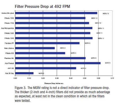
They tested all the filters at the same width and height (16″ x 25″) but the depth varied from 1″ to 4″. They used 492 feet per minute (fpm) as the face velocity because that’s what the ASHRAE filter standard (52.2) calls for. With that face velocity and those dimensions, the air flow rate is 1,367 cubic feet per minute (cfm). (Flow rate equals area times velocity; see my article on the continuity equation for more on this.)
Results: As you can see, there’s not a steady increase in pressure drop as the MERV rating increases. What does happen, though, is that the pressure drop jumps up significantly as soon as you change from the standard 1″ fiberglass filter (MERV-2) to the next level at MERV-6.
They also found “a definite trend toward lower air flow with higher-MERV filters for systems using PSC motors.” (PSC stands for “permanent split capacitor.” A PSC motor is the one powering most HVAC blowers. Variable speed blowers have electronically commutated motors, ECMs.)
The final result I’ll mention here is that they didn’t see as much difference as they expected for filters of different depths. For example, “the 4-inch Filtrete 1550 (MERV 12) was only marginally better than the 1-inch Filtrete 1700 (also MERV 12) and the two other [1-inch] MERV 11 filters of the same brand (1000 and 1085).”
Study #3
Article: The Effects of Filtration on Pressure Drop and Energy Consumption in Residential HVAC Systems (pdf) by Brent Stephens, Atila Novoselac, PhD, and Jeffrey A. Siegel, PhD, HVAC&R Research, Vol. 16, #3, May 2010
This one is an academic paper so if you want all the details, equations, and references to other works, click the link above and download the paper. (Brent was a student at the time he wrote this paper and has a page on his filter research on his website at the Illinois Institute of Technology, if you want to dive even deeper.) They looked at filter pressure drop and energy consumption, both theoretically and using four months of data from two air conditioning systems in a test house in Austin, Texas.
Results: What they found is what you would expect, and in their limited range of MERV ratings tested, they did see an increase with each step up the MERV scale. Here are their results for filter pressure drop:
Low-MERV (<4) 0.10 i.w.c.
Mid-MERV (8) 0.19 i.w.c.
High-MERV (11) 0.32 i.w.c.
So the low-MERV filter is hitting the ACCA design pressure drop. The mid-MERV is twice as much and the high-MERV is three times as much.
They also found that air flow in the high-MERV filters dropped by 7% and 11% in the two HVAC systems compared to the low-MERV filters. Likewise, the mid-MERV filters also showed decreased air flow relative to the low-MERV fitlers, this time 3% and 8% lower in the two systems.
Summarizing the results
As you can see above, the research shows that in general, HVAC systems with high-MERV filters* have a higher pressure drop across the filter. This part is common to all three studies above.
What happens with the air flow depends on what kind of blower the HVAC system uses. In a system with a PSC blower, the air flow drops and energy use doesn’t change much. The Stephens paper cites a 2002 study showing that 90% of all residential HVAC systems had PSC blowers. Certainly that number has fallen in the past 16 years, as high-performance homes and high-performance HVAC systems have become more popular. But I’m sure the great majority of homes still have PSC motors running the blower.
For those with the other type, the electronically commutated motor (ECM), the controls on those motors typically ramp up the motor speed as the pressure increases so relatively constant air flow is maintained. But there’s a penalty. Blowers with ECMs can be more efficient than those with PSC motors when they’re operating against the pressure they’re designed for. But when the pressure is higher, they can end up using more energy than the PSC blower.
So what can you do to be able to use a high-MERV filter* and not suffer a high pressure drop across the filter and the resulting loss of air flow (PSC blower) or increased energy use (ECM blower)? It’s actually pretty simple. You just have to make the filter large enough to have a low face velocity. And that’s where I’m going next with this series. You can get a head start by reviewing the other articles I’ve written on this topic in the past few months, especially the one on the continuity equation.
Next article
The Path to Low Pressure Drop Across a High-MERV Filter
TOOLS FOR MEASURING PRESSURE DROP ACROSS FILTERS
For pros: Digital manometers at TruTech Tools*


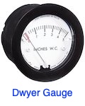
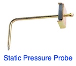
For DIYers: Dwyer magnehelic gauge, static pressure probe, & vinyl tubing at Amazon*
Related Articles
What Percent of Time Do You Spend Indoors?
Which Indoor Air Pollutants Matter Most?
7 Reasons Your Filter Isn’t Improving Your Indoor Air Quality
The Unintended Consequences of High-MERV Filters
* These are affiliate links for Amazon and TruTech Tools. You pay the same price you would pay normally, but Energy Vanguard makes a small commission if you buy after using the link.
This Post Has 29 Comments
Comments are closed.
Great article and studies!
Great article and studies! Can’t wait to read what you have coming next in the series.
This is a great site. I’m an
This is a great site. I’m an engineer so I particularly appreciate the detailed technical info. Now, here is my question. As the MERVE rating increases, is it a function of the density of the filter? If so, can I gang them for better filter performance? So for example, assuming I have the space for ganging filters, which I do, if I gang an 8 MERVE and an 8 MERVE do I get the basic equivalency of a 16 MERVE for filtration efficacy and airflow? I am not concerned about using more electricity due to some reduced air flow. I want higher performance of the combined filter combination without having to search out MERVE 16 filters, which are not all that easy to find in reasonable thicknesses! Thanks! Ed
The effect of adding more
The effect of adding more filters in tandem does not improve the filtration significantly. If the filter 1 captures 90% of certain particles, only 10% will get through and reach the filter2. Filter 2, being the same as filter 1, will capture 90% of the particles that reaches it, which was only 10% of the original number of particles: that is 0.9% of the original pollution. Ergo, the improvement you will get from putting two filters in tandem is below 1% of filtration.
Thanks for your indepth
Thanks for your indepth article in IAQ. Are you familiar with the new PBS series on PROOF IS POSSIBLE?
Did you notice that Greenbuild is now looking at the chemistry of IAQ?
You’re welcome, Dixie. Yes,
You’re welcome, Dixie. Yes, I know of Corbett’s show and have known Corbett for nearly a decade now. I haven’t seen the show yet but I’m sure he does a good job with it. I hadn’t heard about Greenbuild & IAQ but that’s always been part of the LEED rating system for green buildings.
It would seem the increased
It would seem the increased filter size will only slightly help and physically might be hard to retrofit in a widespread manner. And then you still have the excessive static in existing duct systems which is also difficult to resolve. So as Tim the Toolman would say, it may be time for “More Power” with widespread use of ECMs in retrofits. Of course ECMs cost more upfront but an appropriately sized unit generally solves the problem. Plus they run at reduced cfm as much as 90% of the time when paired with two stage or better equipment. But to gain ECM reliability, a known concern, hvac manufacturers need to push whole house surge protection and incrementally increase specified ECM horsepower to reflect the reality of ductwork installations in the USA. Finally better consumer education to the state of the residential hvac industry might be the ultimate solution, allowing market forces to act.
I agree that variable speed
I agree that variable speed ECM motors (not X-13) that can compensate for restrictions can generally solve the problem but, I don’t see it happening.
As a full time HVAC service provider (NCI) trained, I have seen a direct correlation between failed ECM modules and subsequently tested high return static pressure.
Due to a focus on S.E.E.R. (One measure of efficiency) instead of tested efficient, manufacturers provide the smallest motors possible in the equipment. The 2019 FER standard is only going to compound the problem. The amount of ECM motors out there is increasing substantially. I see it everyday!
The only solution I see is proper filter sizing which often requires dual filters. Yet, homeowners and certainly builders and not embracing due to space issues.
I am not sure what Dan means
I am not sure what Dan means that “manufacturers provide the smallest motors possible in the equipment”. Most manufacturers that I know provide indoor air handlers and furnaces that can go up to 1″ ESP, even though we are only required to rate at lower ESP’s. We know that many installers will under size the ductwork and homeowners will use higher pressure drop filters.
Most people don’t realize this, but if you do have a high system ESP requirement due to undersized ductwork or high pressure drop filters, you are better off with a lower airflow rate (perhaps 350 or even 300 cfm/ton rather than 400 cfm/ton). Why? The reduction in blower power is greater than the increase in compressor power so you have higher system efficiency, the lower static pressure results in less duct leakage, it will be quieter, and you will get more latent capacity which can be a benefit in humid climates. So if you have a constant-cfm ECM blower, turn down the airflow rate. “X-motors”, which are ECM motors without the constant airflow rate feature behave more like PSC motors in this respect.
Roy,
Roy,
I am referring to residential equipment; per nameplate specifications the majority of variable speed motors are limited to a total ESP of .5″ W.C. Yes, there are some exceptions, I have seen some rated for a max of .8″ W.C. But, the risk is failure of the controller and reduction in efficiency as the maximum static is reached or exceeded. I agree that setting a reduced CFM may solve that problem. If you ever see a residential data plate with total external static pressure of 1″ W.C. please post it.
Dan, I have worked for 3
Dan, I have worked for 3 different residential furnace manufacturers so far, and all of them have furnaces that are able to go up to 1″ ESP. I don’t want to mention brand names on this web site. I guess that I was unaware that we even put ESP limits on a nameplate, so I will have to check into that. I know that we would all like our customers to design systems at 0.5″ ESP or below, but we also know that many do not. So maybe the nameplate is a CYA thing. As for why we limit the maximum ESP, it is not because of risk of controller or motor failure. PSC motors automatically unload at high ESP’s, and ECM motors have electronic protection that will limit their speed at high loads when necessary. So you can abuse them with poor duct design, but they will protect themselves. We do not like unnecessary warranty replacements.
I appreciate the insightful
I appreciate the insightful comments. I plan on gathering some data on future failures I encounter. Be well.
I have found many Ecm motor
I have found many Ecm motor failures that were suffering with high static pressure. The furnaces where not maintained. The filters and blower wheels plugged. It was only the bell end capacitor that failed and replacing the bell end was not difficult. Some manufactures however will not sell you only the bell end.
I have been in the HVAC
I have been in the HVAC Industry going on 40 years. In the real world we don’t see a huge failure of ECM motors. My own furnace is 12 years old, has a 4″ media filter and runs 24/7/365. A simple indication that an ECM Motor cannot overcome the static pressure of the system is called “hunting” Because the ECM responds to a torque sensor rather than static pressure, it will start surging up and down in RPM if it can’t maintain the selected CFM. We see horrible duct systems and yet the ECM motors overcome the resistance almost always. Having said that, a poorly executed duct system will probably have a negative effect on motor longevity whether PSC or ECM.
Hello, I wonder if any of
Hello, I wonder if any of the studies measured dirty filters? That just might have an effect on things!
Yours, Larry
In my opinion, air filters
In my opinion, air filters should be at the return air grills, not at the equipment. This location has several advantages. It helps keep the return air ducts clean. It is usually a simpler location for replacement (avoid high ceiling returns). In a properly designed system with my return grills, there will be more return grill area, thus lower face velocities and pressure drop. The only downside that I see is that this will lower the pressure in the return ducts even further, but if they are properly sealed this should not be a problem.
In January you said: “You
In January you said: “You just have to make the filter large enough to have a low face velocity. And that’s where I’m going next with this series.”
It’s July and I’m anxious to read about your recommendations for filter size!
Thank you for the great series!
Emile
Emile,
Emile,
I wrote the article you’re looking for in April. Here it is:
The Path to Low Pressure Drop Across a High-MERV Filter
I guess I should add a link to the article above, too.
Thank you. I was also looking
Thank you. I was also looking for this article and do suggest you link it to your Precious one. Glad I read the comments and found it.
Is there any evidence that
Is there any evidence that the higher MERV filter on a cold air return will dampen motor/blower sound?
Layman homeowner here – I
Layman homeowner here – I note higher MERV rated filters create duct rumble, but only with some filters. Clearly, not all filters are the same.
Via this site and the trails it led me down, I’ve learned two MERV 11 filters can have the same filtering capacity, but one might allow more air to transfer. From that information, I did a bit of digging and one very well known company provided a demonstration of their MERV 13 filter up against others. The flow capacity was, VISUALLY, significantly improved, but you paid nearly three times as much for their high end filter.
Sadly, most of us homeowner types don’t want to or don’t have the time to learn the basics about different filters, let alone the means of monitoring and testing them.
I wish more companies pushed manometers and Magnehelic gauges being installed, as well as simplistic info brochures explaining why jumping to a MERV 13 from a 50 micron filter can be problematic, or letting a filter double in depth due to dust build up (saw it, as a handyman – the furnace still worked (kind of).
Sadly, even so called reputable companies can be less in-the-customer’s-best-interest. When I moved into our current house, I noted one of the flex ducts was crushed in half, because their “expert installers” didn’t cut the basement paneling sufficient to allow the duct to pass.
They, also, put the return in the floor, in a traffic area, something no one could convince this layman was a good plan.
Question – the restriction of
Question – the restriction of air flow – do you see this with all High Merv filtration systems? I was considering putting in the IQair Perfect 16 whole house filtration system. I would appreciate any info you can send me to help me make an informed decision. Can you make any recommendations if this is a good thing to do in my home or not? Thanks
My background has been in
My background has been in developing diagnostic tests for infectious diseases. I have spent a lot of time in biohazard suites and clean rooms and I have a great respect for the HVAC professionals who design and maintain those systems. The main principles in biohazard areas seem to be focused on airflow (room changes) and air filtration. What if HVAC were used as an offensive tool in battling the pandemic? The virus infects persons who don’t know they have it. The worst-case scenario is probably someone sneezing into an office, school, church or store. Most of the viral load is carried in droplets that fall to earth within 3 feet (the basis for social distancing). The smaller droplets are airborne as they continue to float and to be diluted by room air. Data says that 1000 individual virus are needed to cause infection. Those can come from doorknobs, any contaminated surfaces and from virus floating in the air.
The role of HVAC would be #1) use airflow to dilute and whisk away airborne virus and #2) remove virus from return air with MERV 13 or higher filters so that supply air is not spreading
virus across the entire facility. The discussion of filter area and pressure drop illustrates how HVAC experts are considering all the parameters that can be tweaked, without driving costs to unacceptable levels.
Driving airflow and room air changes to the max while still being able to use a MERV 13 or higher filter is the direction that would protect the most people. What would be the effect of
other theoretically heretical adjustments to the system? Continue to massively increase filter surface area, run higher face velocity, use the max blower speed? What combination gives the highest number of room changes while still maintaining filter integrity? I appreciate your consideration and look forward to your comments.
How do I find this
How do I find this information on my HVAC system equipment?
Robert, you will find the
Robert, you will find the model number on many furnaces and boilers by lifting the door off. It will be on on either side, below the gas burners or on the face plate. On some furnaces it may also be found on the outside of the furnace. Your air conditioning tag, if not faded away, can be almost anywhere on the unit and is sometimes hidden down by where the copper refrigerant lines connect to the unit. As an alternative they may be listed on a service ticket if you have one. Use about 5 characters of the numbers a space and PDF “58STA PDF”. If you play around with that and don’t find anything chances are it’s time to replace your equipment. To tell how old the equipment is google the manufacturer’s serial number nomenclature, “Rheem Serial Number Nomenclature”. If you can’t do that there are 2 hacks. Try to find the 4 digit date code on components “3602” would be the 36th week of 2002. Components get replaced so you have to find at least 2 from the same year and that’s still not a guarantee. The other hack will only get you close. Look for a year after ANSI at the bottom of the furnace tag. This is NOT necessarily the year the furnace was made this means the furnace meets the ANSI Standards for that year “ANSI – 2001”. Those standards change every few years so that just gets you close. Good Luck
I haven’t seen this mentioned
I haven’t seen this mentioned anywhere, but since my downflow furnace employs two filters side-by-side, isn’t that equivalent to using a filter that’s double the specified cross-section, and shouldn’t I expect the filter to cause only half the pressure drop specified or measured in upflow furnaces? Else, what am I missing?
Oh, whoops. Re: my last and
Oh, whoops. Re: my last and as-yet unmoderated/unposted comment, and my question “what am I missing?” I see now that I was missing simple geometry in calling the V-configuration “double” the area. At a 45 degree slant, each filter is about 1.4x the area of a filter spanning the same half of the duct horizontally or at 0 slant. So if I’d remembered my geometry, I’d have expected two filters in a V to present about 2.8x the area as one filter horizontally spanning the same duct, and to diminish the pressure drop by less than a third…which doesn’t seem quite so remarkable or noteworthy. Also I see now I didn’t think about the possibility that the V-filter box selected for any given downflow furnace might not be the same dimensions as for the horizontal box in the upflow version, but sized to be equivalent.
i.e. “equivalent” not in
i.e. “equivalent” not in cross sectional area but with filters in place and with regard to the pressure drop to be expected (sorry for so many posts)
Since I can’t delete my
Since I can’t delete my original or subsequent questions and naive hunches, let me just recant them. I now suppose it’s more complicated than I did either the first or the second time
My question is regarding the
My question is regarding the drop of pressure due to the filter: if a filter that is 20x20x1″ has approximately half the filtering surface of a filter that is 20x20x2″, would that mitigate the pressure drop? I am asking because I use a system for indoor pollution that consists on attaching a filter to the front of a 20×20 square fan.
Thank you in advance.