The Path to Low Pressure Drop Across a High-MERV Filter
Last August I began a series of articles on filtration and indoor air quality. You can find the list of them at the bottom of this article but let’s do a quick review here: We spend a lot of our time in buildings. A lot of indoor pollutants are generated in the kitchen and not removed by the range hood. The consensus among indoor air quality researchers is the particulate matter that’s 2.5 microns or smaller (PM2.5) is one of the worst for health. And finally, good filters (i.e., MERV-13) can remove a lot of the PM2.5 and other pollutants but experience as well as studies show they often don’t, for a variety of reasons.
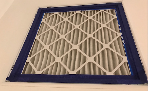
So how do we fix this situation? How can we get a high-MERV filter and have it do a good job of filtration without causing problems with the air flow in the heating and cooling system? The answer is simple: Make the filter big enough. John Semmelhack, owner of building science firm Think Little in Virginia, spoke about this topic last year at the North American Passive House Conference in Boston. Also last year, we got a new Mitsubishi ducted mini-split system here in the Energy Vanguard office in Georgia (meticulously installed by PV Heating and Air). Let me show you what’s possible.
High-MERV filters with low pressure drop
Semmelhack spoke about ducted mini-split heat pumps in Boston and towards the end of his talk he got to the topic of filtration. (Download the presentation and see the filter section starting with slide 25.) He used a 2″ deep MERV-13 filter in a filter grille. The ducted mini-split they used was a one ton system moving 400 cubic feet per minute (cfm) of air. The pressure drop across the MERV-13 filter was an astoundingly low 0.0274 inch of water column. Yes, really!
What was their secret? They used a 20″x20″ filter. That’s all. Just make the filter bigger and you get a lower pressure drop. The key is to look at the ratio of the filter area to the air flow rate. In their case, the filter area was 2.78 square feet (sf) so the ratio comes out to be 2.78 sf ÷ 400 cfm = 0.007 sf/cfm. Using the nominal air flow rate of 400 cfm/ton of capacity, we can make the number look a little friendlier: 2.78 sf ÷ 1 ton = 2.78 sf/ton.
Hang onto that calculation. I’ll come back to it in a minute.
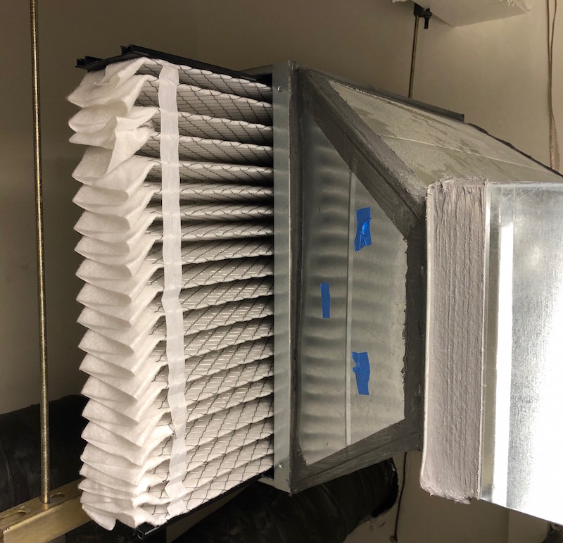
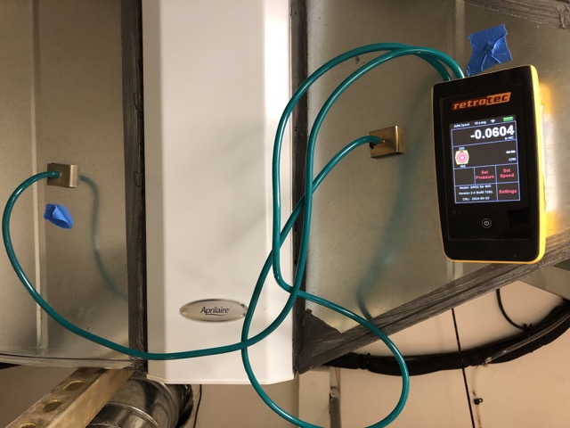
In our office, we got a similar result, although our pressure drop is a bit higher. We have an Aprilaire filter that’s also 20″x20″ but it’s a 4″ deep filter in a cabinet near the ducted mini-split air handler. Our pressure drop is 0.0604 i.w.c., as you can see in the photo below. That’s higher than Semmelhack achieved with his system but still really low compared to what you might expect.
The Air Conditioning Contractors of America (ACCA) Manual J load calculation protocol says to allow 0.10 i.w.c for a filter…and that’s generally for a standard 1″ deep MERV-2 filter, not a 2″ or 4″ MERV-13. Ask contractors what the pressure drop across a high-MERV filter is and they’ll probably tell you something like 0.25 i.w.c.
When we measured the air flow in our system, we got 363 cfm, so our ratio of filter area to air flow is 0.008 sf/cfm, or 3.1 sf/ton when converted using 400 cfm/ton of capacity. We have more filter area per unit of air flow but we got a higher pressure drop than Semmelhack. Some of you building science geeks are wondering about that, I’m sure, and so am I.
The main difference between the two systems is that our filter cabinet is installed in the middle of the return duct whereas Semmelhack used a filter grille. We installed a filter grille, too, and currently it doesn’t have a filter in it. We’ll be testing that at some point, though. Another difference between Semmelhack’s pressure drop and ours is that he used a 2″ deep filter and ours is 4″ deep. We’ll keep measuring our pressure drop and I hope that with more data, our average pressure drop will be lower.
But let’s not get hung up on why our pressure drop is higher than Semmelhack’s. Getting a 0.06 i.w.c. pressure drop across a MERV-13 filter is still great. The key to whether it’s a good number or not is how well it fits in with the total pressure drop in the system compared to what’s allowed (the total external static pressure, or TESP). More on that in a future article.
A simple rule of thumb for low pressure drop across a high-MERV filter
I’ve shown you data from two MERV-13 filters now. Both are much lower than you’d measure across many of the MERV-13 filters installed in the wild, and I’ve given you the key to achieving similarly low pressure drops. It’s simply to increase the filter area relative the air flow rate.
The two systems described above had ratios of 2.8 sf/ton and 3.1 sf/ton. You don’t have to go that high, though. David Butler, an HVAC designer and frequent commenter here, said he uses 2 sf/ton as his guide.
Home performance contractor extraordinaire Mike MacFarland of Energy Docs in Redding, California does it a bit differently. He uses 250 feet per minute (fpm) as his absolute maximum face velocity for air moving across the filter but generally sticks to 200 fpm or lower. The conversion from face velocity (ft/min) to filter area per ton of capacity (sf/ton) is straightforward using the equation q = A x v. (You may recognize the product of area and velocity from the continuity equation for air flow.) The answer in this case is that 200 fpm = 2.0 sf/ton in this case, the same number David Butler uses. MacFarland designs for conventional heat pumps rated for 0.5 i.w.c. total external static pressure (TESP) and had never had a system come in at a TESP higher than 0.35 i.w.c., with most of them measuring 0.30 i.w.c. or less.
With smaller capacity mini-split heat pumps, getting filter sizes to 2.5 or 3.0 sf/ton isn’t that hard. With conventional systems, it’s not so easy. With a 2.5 ton system at 3.0 sf/ton, for example, you’d need 7.5 square feet of filter area, or a 30″x36″ filter, but you’d have a hard time finding one that size so you’d have to install two 18″x30″ filters. You can do it if you really want to, but if you use MacFarland’s rule of 2.0 sf/ton, the resulting 24″x30″ filter (or equivalent) is much easier to find space for and you can still get a low pressure drop.
So here’s your rule of thumb for filter sizing:
Filter Area = 2.0 square feet (or more) for each 400 cfm of air flow
Do that (and size your ducts properly) and you shouldn’t have to worry about high pressure drops across your filters…at least not when the filters are relatively clean.
A shoutout to our sponsors
As mentioned at the top of this article, we got a new Mitsubishi ducted mini-split (and two ductless units) installed in our office. Mitsubishi donated the equipment for this project, and PV Heating and Air, a home performance contractor in Atlanta, donated their labor. Ultra-Aire donated a ventilating dehumidifier for our office and now that we head into warmer, more humid weather, I’m excited to see the difference it makes in our indoor air quality and comfort. Finally, Aprilaire donated the filter cabinet and MERV-13 and MERV-11 filters. We like these companies and recommend their products and services.
Allison A. Bailes III, PhD is a speaker, writer, building science consultant, and the founder of Energy Vanguard in Decatur, Georgia. He has a doctorate in physics and writes the Energy Vanguard Blog. He also has a book on building science coming out in the summer of 2022. You can follow him on Twitter at @EnergyVanguard.
Other Articles in This Series
What Percent of Time Do You Spend Indoors?
The 2 Main Problems With Kitchen Ventilation
Which Indoor Air Pollutants Matter Most?
7 Reasons Your Filter Isn’t Improving Your Indoor Air Quality
The Unintended Consequences of High-MERV Filters
Do High-MERV Filters Always Reduce Air Flow?
NOTE: Comments are moderated. Your comment will not appear below until approved.
This Post Has 86 Comments
Comments are closed.
Very good Allison. And now
Very good Allison. And now for part two – at what pressure drop across the filter does it need to be replaced? Then part 2b, what season is best for filter replacements? Could winter be better than summer?
Great questions, Danny. I’d
Great questions, Danny. I’d say the filter needs to be replaced when the TESP gets too high so you’ve got to know how much slack you have in the system. Of course, it also depends on whether you have a PSC or ECM blower. With the former, a loaded filter reduces air flow but doesn’t cost you in energy. The latter will ramp up to maintain air flow, adding to your energy use as the filter loads.
I suspect your question about the best season to change the filter is related to humidity control. With a PSC blower, as mentioned before, the air flow goes down as the filter loads, and in a humid climate that’s a good thing for removing water vapor as the coil gets colder. But you have to be careful that the air flow doesn’t go so low that you freeze the coil.
And another benefit of a loaded filter is that it filters better.
For anyone not monitoring their static pressure and air flow, it’s best just to change the filter regularly.
Interestingly, the old ASHRAE
Interestingly, the old ASHRAE 52-76 had a final PD of 1″ wg. Constant flow ECM’s will meet the challenge up to 1 inch, even if it take every energy dollar you got. Constant torque ECM is the worst of both worlds. It’s schizophrenic – “I want to be a fully modulating motor. No wait, I want to act like a PSC……”
I am really curious what the upper limit of TSP is and why it is an upper limit. Most gas furnaces say TSP not to exceed .50. Some heat pump air handlers say .25. But I have never had any manufacturer tell me why.
Danny, I have been wondering
Danny, I have been wondering why a Carrier 59TP6 VS Furnace is not ramping up to overcome the 0.7 static pressure of the system (yeah i know – all typical residental texas flex duct). Then I looked at the fan curve and was surprised, because I would have assumed that the CFMs should be constant, regardless of TESP. But e.g. on the 800 CFM at 0.5 TESP nominal setting the CFM goes down to 770 CFM for 0.6 TESP and 735 CFM for 0.7 TESP.
Is this motor what you refer to as an ECM that wants to behave like a PSC? Why in the world would Carrier install this and call it a VS furnace when it is not maintaining CFMs even though the motor is capable of ramping up? Just to save a few dollars on some logic?
See page 6 for air delivery CFM per TESP for this furnace in case you want to see the charts yourself.
https://dms.hvacpartners.com/docs/1009/public/09/59tp6a-02pd.pdf
I feel your frustration
I feel your frustration Robert. The chart shows the behavior of a constant torque ECM (X13). The curve gives it away. It mirrors a PSC but doesn’t drop off as dramatically. Its all in how they program the microprocessor. I have the same question as you. WHY?????
Yeah i feel like it is
Yeah i feel like it is deceiving marketing too. When you read the website and brochures it always states “Variable-speed, high-efficiency, ECM blower motor” for this model. There is nothing besides the detailed fan performance table that would suggest this blower behaves differently from the Infinity furnace which has the true constant CFM VS motor. That one also says “Variable-speed, ECM blower motor” in all marketing materials … just doesn’t feel right.
Robert, It is an ECM
Robert, It is an ECM (electronically commutated motor). So it would be described as a variable speed, brushless motor that uses about 1/2 the energy as a PSC. They just come in two flavors. Some manufacturers allow you to choose constant torque or constant flow. Constant flow is always more $$. If you are accustomed to using constant flow, it is unsettling the see this performance.
BTW, if you are using the SEZ, it only has .20 inches wg TSP. So you must be judicious with the duct resistance.
Hopefully I can clear up some
Hopefully I can clear up some of the confusion. ECM blowers come in more than two flavors. In particular, variable speed is NOT synonymous with constant flow, i.e., not all variable speed blowers have the constant flow feature. You can tell immediately by looking at the blower performance table. VS blowers that aren’t constant flow drop off in airflow as static increases, as with non-variable ECM blowers. Also like non-variable ECM’s, these motors are ‘constant torque’ (within a limited range). The 59TP6 furnace Robert mentions is an example. So I suppose you could say there are 3 flavors of ECM’s: non-variable constant torque, variable constant torque, and variable constant flow. Most variable speed blowers have the constant flow feature, which is probably why there’s so much confusion on this point.
BTW, constant flow blowers attempt to maintain the selected CFM within the operational external static range, but you’ll see some fall-off at the top end.
Danny wrote: “Constant torque ECM is the worst of both worlds.”
I beg to differ. It’s important to keep in mind that (all else being equal) all three flavor ECM’s have the same efficiency at a given static pressure-CFM combination. I typically specify non-variable ECM’s for applications that don’t require variable speed since VS blowers cost significantly more. Why speed big bucks on constant flow when the application doesn’t demand it?
As an aside… In the real world, constant flow blowers are often misused by dealers who like the fact that they’ll deliver the correct airflow through their overly restrictive ducts. SEER ratings are meaningless when you operate at high static. Sigh.
David,
David,
I “beg to differ” with your “beg to differ.” And you will likely “beg to differ” with my “beg to differ”. So let’s agree up front to “beg to differ”.
I hate varying indoor airflow. And you know I am OCD about this. It is not consistent with good design.
Just yesterday, I completed a load on a 2 story, 3,300 sq. ft home with a 14,400 btuh heat gain (sensible 10,400+4,000 latent). My best guess is we will have 24 supply terminals that must accommodate a whopping 650 CFM. So I go about selecting these 4″x2.5″, 6″x2.5″ etc bar linears to provide some semblance of throw and along comes your X13 to trash their performance when the filter loads with four particles of 2.5 um of skin flakes, insect parts and Ovaltine. Considering the consequences and the over all budget, a constant flow blower isn’t “big bucks”. I am not using ECM’s for energy efficiency anyway.
Then I would say your
Then I would say your application demands constant flow. I don’t have a problem with that, but likewise, you shouldn’t discount the usefulness of constant torque ECM’s in applications that don’t demand constant flow. Not everyone is OCD about the impact several hundredths of an inch of static on system flow as the filter loads.
In any case, my comment regarding efficiency was directed at the folks who upsell or specify variable speed AHU’s (even with single stage equipment) based on the incorrect assumption that variable speed ECM is inherently more efficient than non-variable ECM.
We had up-speced to VS
We had up-speced to VS because of the dehumidify feature, being in the Houston climate. The system dehumidified so well that I was surprised how well this works. But then I also realized that I don’t get full cooling capacity because the system couldn’t get to design temp of 75 on a typical 96 design temp day. I got the HVAC contractor to bring out a manometer (he had to borrow one from a friend) and showed him where to take the readings (he said he never uses it) and we realized the system static was 0.7. I first thought, no big deal, the VS blower just works harder than for the designed 0.5 … but then why do i not get the full cooling capacity? Took me a lot of research to realize that my VS blower is the constant-torque variety. And now I also understand why I get such good de-humidification …
The builder HVAC guy still has no solution. I would love to try to get to 0.5 design as hoped. I asked him to redo the return plenum so that the two 12″ flex duct don’t bend 180 degrees before coming into the return, but he insists that’s not the problem and that the system is operating just fine.
David, by any chance do you have a good reference for a Houston HVAC contractor? I remember reading that when you do designs you sometimes also interview various contractors so maybe you have come across a reputable Houston HVAC contractor? I won’t get any further with the builder and his contractor. I already called 5 different companies with great reviews on google and when talking to them on the phone and asking about how they would measure airflow, not one had an idea besides measuring Delta-T. When I asked about static pressure they said that’s not something they typically measure … am I just unlucky or is this really the state of the Houston Residential HVAC industry?
Robert,
Robert,
This is not a static problem. It’s an airflow problem, reflected by the static and the characteristics of constant torque ECM’s. Moreover, you are likely getting close to full capacity or 98% or so. What you are seeing is more total capacity being used to remove moisture. Hence senisble capacity is down and the thermostat isn’t gettingsatisfied.
FYI, more airflow = more capacity and higher sensible heat ratio. Lower airflow = a wee bit less total capacity and a lower SHR.
If the contractor knows so little about system performance as you state, my bet is the refrigerant charge is likely incorrect as well. Proper refrigerant charge metrics are always assumed for “x” CFM (typically 400) per ton. So if your airflow has dropped to 300 or 350, the contractor, who apparently doesn’t understand airflow, see low suction pressure and is duped into thinking the unit was undercharged. Then he runs to get the R-410A jug and packed more in. After-all more is better…….Overcharging will definitely reduce capacity. I have seen it hundreds of times.
This is one of the primary rebuttals from the contracting folk in discussing rightsizing. The unit is under airflow, resulting in overcharge, creating a warm house. Then they say “You see, I tried to tell you we should have installed that 7 1/2 ton unit”.
I’m anxious to see David’s response.
@Robert, although we can’t
@Robert, although we can’t diagnose your system from afar, Danny’s point about impact of airflow on total capacity and charging is spot on. You can increase sensible capacity by increasing airflow at the expense of some dehumidification capacity. It sounds like you may be able to give up a bit of dehumidification without sacrificing comfort.
If refrig charge is off (because tech didn’t understand airflow vs. charge), then fixing that should free up some additional capacity. You can’t properly charge a system based on pressure unless airflow is correct and ambient conditions within an acceptable range. Best to charge by weight.
Regarding airflow / high static, I’d want to know the supply and return static breakdown before making a recommendation, as well as the pressure drop across the filter. But in my experience, the return side is often the culprit and is usually the easiest to fix. I can’t comment on the usefulness of rebuilding your return plenum to eliminate elbows without seeing how that would work, but you should look for a way to add another return and depending on current filter size, increase the surface area.
Lastly, the best way to ‘have your cake and eat it too’ is to reduce the moisture load on your system. In humid climates, that means reducing infiltration (through strategic air sealing). Tightening your enclosure is a ‘two-fer’ as it also would reduce the sensible load. You can further reduce sensible loads by keeping blinds closed on windows that aren’t shaded by trees and overhangs, especially on south and west facades. Direct sunlight into the house is your enemy during cooling season.
I feel your pain regarding the state of the industry. Unfortunately, I can’t help with a referral. I suggest starting with the NATE referral engine (natex.org). It sounds like you have a general understanding of the concepts discussed in this thread, so ideally you should talk with prospective techs before hiring someone, but that’s easier said than done!
Thanks David and Danny. I
Thanks David and Danny. I actually do have the static pressure measurements, because I showed the HVAC tech where to put the probes and wrote down the numbers of the various tests. I also cross checked various combinations and did the math to make sure we got it all right.
Total across system: approx 0.7
Return: 0.23
Filter: 0.10 (Honeywell F100 4x25x16 – MERV11)
Coil: 0.12
Supply: 0.25
Infiltration per builder was 2200cfm50 which came out to around 4 ACH50 (our building code unfortunately still allows 5 instead of 3 further north). Duct leakage should not be an issue since they all run in the open web trusses and the AC system sits in a storage room inside the conditioned space on the second floor.
I designed the house myself with no west facing windows and all south facing windows having 2.5 ft overhangs, so no direct sunlight on the windows from April-October (though I did opt for thermally broken aluminum which I know have a big penalty, but we wanted lot of large windows for natural daylight – all of that was in the Manual J)
The return is clearly not ideal, but no idea whether getting the 180 degree u-turn in the flex duct away and instead have a 90 to the side of the plenum will make a huge difference on the static or not. The link below has some pictures of the “beautiful” flex duct install, but at least I got them to put in hard metal 90ies at the supply plenum. Not on the return though where they put the hole into the subfloor in a bad spot which required this weird horeshoe bend on one of the two 12 ” flex returns. https://hvac-talk.com/vbb/showthread.php?2196258-New-Home-AC-System-unable-to-reach-set-point-builder-quality-HVAC-install
There is also an issue with the coil cooling not evenly and one side of the supply plenum being warmer than the other which is even noticeable in the ducts. They first thought it was a bad coil, replaced it, same story. Then they put in a transition between upflow furnace and coil: a bit better, but still 10 degree temperature difference between the duct exiting to the right of the plenum (50 degrees) vs. the left (60 degrees) while the return temp is 75.
By now I feel like I know way too much about AC systems already for a home owner. I just need to get a really good and reputable HVAC technician, then I’m sure my problems can be fixed. As David suggested, I have already called 8 companies and insisted to talk to a tech prior to having them come out, about half of them there is no way to talk to a tech, you can’t get passed the scheduling assistant without paying for a $80 diagnostic on-site visit. The others I did get the tech on the phone but no one appeared really competent. The minute I tell them it’s 2 tons for 1850sf they tell me the system is just too small. *sigh* One guy that got referred to me as a “duct system expert” asked me how many take offs from the plenum. When I told him 2×10 inch, 1×9 inch and 1×8 inch he told me that clearly my supply ducts were too large which was creating issues (yeah I’m sure that would help the air flow to reduce the ducts and increase the static pressure even more :S) … sorry for the ramble/rant … you would think in a city where 9 months of the year the AC runs and dehumidification is a key requirement, there should be a huge talent and knowledge pool for HVAC …
Any tidbits of information
Any tidbits of information would be appreciated, from the standpoint of a woodworker setting up lines in a shop.
You mentioned “a whopping 650 CFM,” which is huge for the system you described. More so when you consider all those lines have to be running at the same time.
In my shop, I have two three horse power dust collectors. That is their actual power rating, off a 240 volt line. Even with that kind of power behind the blades, we have to work hard to get that kind of CFM at three pieces of equipment in relatively short runs.
To that end, we use smooth wall pipe, since any ridges and such on the interior of even 8″ hoses beats the hell out of the numbers. Too, we avoid bends and when we have to do a drop from the ceiling, we use long, sweeping bends, since bends, also, beat down the numbers.
All this is done through filters that take out particles down to a half to one micron in size.
Of course, we use impeller systems that can take a hit from a pieces of wood, rather than a squirrel cage, but I have to wonder at the tricks we might adopt to up our numbers, since they are critical to catching both the fines and the larger pieces.
Again, any food for thought that might cross over would be helpful.
Its about temp rise!with Poor
Its about temp rise!with Poor air flow you leave heat in the coil- heat pump or in the exhaust pipe for gas furnace. Also you can shorten heat exchanger life span by having low temp rise. Air flow rules
Hello, I am a consumer. You
Hello, I am a consumer. You folks are all smart knowledgeable HVAC engineering pros. I have a possible issue of concern on my two Lennox 2 and 4 ton Lennox XC21 units and also two Healthy Climate units and two APCO UV systems with two lights each. Split system between home exterior with air handlers and Healthy Climate (MERV 11) and APCO’S in garage. Installed April 2018. Florida 21 months ago.
First I had to say the folks that sold and installed the system were great. They were concerned about static pressure so limited the MERV to 11. I was told I no longer needed my interior return filters. 3,500 SF home 4 returns. High ceilings.
A couple weeks ago and only because I had to get up to a high storage deck and I happened to be near the largest return and noticed the old blue filter was still in the return. I dropped the grill and dust literally fell on my face. So it occurred to me today to check the other returns and sure enough the old filters were in place and filthy as two years old.
I am worried there may have been some residual and future affect on longevity of the units. With everything it was $23,000. I whole lot of money in my world. But worth it as we live on wooded preserve and tons of allergens. What do you recommend? How were the units able to function? And finally I changed the Lennox MERV 11 filters every six months and wondered why they were almost perfectly clean. Now I know why. Any advice? Thanks very much! Also, sorry if I posted this in the wrong place.
We typically monitor
We typically monitor crawlspaces and sealed attics as well as living spaces to verify they are in a good comfort range. We do this with Z-Wave products. Are there any z-wave products available that can read iwc? I would love to monitor and track the pressure inside of duct work. A true “Time to change your filter” notification would be fantastic.
Hello,
Hello,
I wondered if you could recommend a filter size [length and width] which would allow good flow [low pressure drop] for a MERV 13 or even MERV 14 if possible. I am a part owner in an office building in San Francisco and I was wanting to upgrade to a higher level filter for our HVAC systems. We have four floors [about 2000 square feet each] and they each have their own HVACn unit. Our HVAC company would have to build new filter slots I believe because currently they can only accommodate a 1 inch thickness and I think the higher MERV filters are two inch depth at least. Thank you for any thoughts. Michael Bronzo
Michael, you haven’t stated
Michael, you haven’t stated what the air flow in each unit is so I can’t give the length and width of the filter you need. The rule of thumb in the article can you guide you to the correct size, though. Just make sure each one is sized at 2 square feet of filter area (not counting pleats) for each 400 cfm of air flow.
Replacement filters for
Replacement filters for existing filter channels in existing HVAC units will normally have approximately 450 – 550 FPM face velocity as a part of OEM equipment design regarding adjacent coil maximum face velocity (water carry over). Oversized filters will measure lower pressure drops as their face velocity falls. Where face velocities are closer to the 500 FPM median, filter material and pleat designs will be the way to balance pressure drops against MERV. Filter loading qualities can effect length of life.
Hello, I am a consumer. You
Hello, I am a consumer. You folks are all smart knowledgeable HVAC pros. I have a possible an issue of concern on my two Lennox 2 and 4 ton Lennox XC21 units and also two Healthy Climate units and two APCO UV systems with two lights each. Split system between home exterior with air handlers and Healthy Climate (MERV 11) and APCO’S in garage. Installed April 2018. 21 months ago.
First I had to say the folks that sold and installed the system were great. They were concerned about static pressure so limited the MERV to 11. I was told I no longer needed my interior return filters. 3,500 SF home 4 returns. High ceilings.
A couple weeks ago and only because I had to get up to a high storage deck and I happened to be near the largest return and noticed the old blue filter was still in the return. I dropped the grill and dust literally fell on my face. So it occurred to me today to check the other returns and sure enough the old filters were in place and filthy as two years old.
I am worried there may have been some residual and future affect on longevity of the units. With everything it was $23,000. I whole lot of money in my world. But worth it as we live on wooded preserve and tons of allergens. What do you recommend? How were the units able to function? And finally I changed the Lennox MERV 11 filters every six months and wondered why they were almost perfectly clean. Now I know why. Any advice? Thanks very much!
A MERV-11 filter will
A MERV-11 filter will eventually achieve HEPA level filtration as the trapped particulate (filter bed) establishes itself over time. I was fortunate to work with some of the best minds in air filtration and particulate removal. I’ve been retired for 7 years. This is not a plug for their product but, most of you have probably never thought of this filtration concept, removing particulate and returning it back to the atmosphere prior to the “Precleaned” air passing through the filter media. Google RESPA-CF and enjoy the journey.
I’m a 100% layman, so talk
I’m a 100% layman, so talk slow to me 😉
To set the stage: I have three dust collectors in my shop. Two are three horse units. Both of those have solid collection containers under them (e.g., plastic bags or drums). One has two upper cartridge filters and the other has two one micron bags. The latter only reaches that efficiency after loading with dust. As such, fully cleaning the bag reduces filtration efficiency.
Even though the bag allows air to pass more freely than the cartridge filters, even without equipment, the difference in draw between the two units is notable, because of the increased filter area of the cartridge/canister filters, which is a few times greater than the area of the bags. Being able to note a difference grows as the bags and canister filters load. Again, the canisters rule.
I am just learning the whys and wherefores of HVAC systems, at least at the curious layman level. This information is VERY helpful supports the probability my schemes will not be wasted efforts
Just following, I had the
Just following, I had the same question as Danny.
I’m in the final design stage for my new construction home unit using the Mitsubishi concealed cabinet model.
Lee, the recommendation by
Lee, the recommendation by John Semmelhack in his comment is the best advice I’ve heard on that issue: Replace the filter when the pressure drop across it doubles…or until you can’t stand how dirty it looks. Of course, that method shouldn’t apply to a filter that’s already causing the whole duct system problems but since you’re putting in a ducted mini-split, I’m sure you’ll have a well-designed duct system with low TESP.
oops, Lee I made a comment to
oops, Lee I made a comment to Robert that was intended for you. If you are using the Mitsubishi SEZ air handler, be careful. It only has .20 inches wg of total static pressure available. So the ducts (filter and terminals) must be extremely aerodynamic.
Danny, I’m using the SEZ and
Danny, I’m using the SEZ and did notice the 0.2″ ESP. I was originally considering having to do an independent HEPA, but I will check to see if the oversized MERV 13 can be incorporated into the SEZ. Wondering if it will help to toss out the SEZ factory filter since it would probably stay spotless anyway. Any thought?
Lee, the Mitsubishi ducted
Lee, the Mitsubishi ducted air handler we installed is an SEZ unit. Even with 0.06″ across the MERV-13 filter, out total static is only about 0.1″. So yes, it’s certainly possible to do MERV-13 in a low static air handler. And yes, toss the factory installed filter.
One more point: As with most air handlers, there are several settings that determine what fan curve is used, and 0.2″ is what you get on the highest setting. But the system comes from factory set for the next highest setting, 0.14″.
Now if we could just get the
Now if we could just get the manufacturers to build in enough smarts to measure the pressure drop effectively and recommend filter replacements based on actual need as opposed to every X days.
Wouldn’t that be nice!
Wouldn’t that be nice!
You would think a 4″ MERV-13
You would think a 4″ MERV-13 filter would do a decent job at filtering room air. Did it? No mention of before/after PM2.5 measurements. Also – from the photo it looks like the Aprilaire filter cabinet is in-line with the ducted return, so that means dirt in the return ducts prior to the filter and need for some periodic cleaning. What about the ductless units you also had installed?
David, we just got the system
David, we just got the system finished recently and haven’t set up testing for everything yet. Also, we don’t have PM2.5 data from before the system was running but we can see what happens with the system turned off to get an idea of the baseline.
Yes, there is a little bit of ductwork upstream of the filter you see above, but the grille is about 10′ off the floor and it’s a filter grille. I prefer filter grilles to keep the ducts clean, but we set it up this way so we can do some testing on different configurations. And we can always use a low-resistance filter at the grille as a pre-filter.
The ductless units have their factory-installed filters.
Our general rule is that when
Our general rule is that when the pressure drop across the filter doubles from the initial, clean pressure drop, it’s probably time for a change. With big, deep filters this can take a loooooooong time, and the filters will look absolutely disgusting well before the pressure drop would indicate that it’s time for a change.
In my presentation slides that Allison linked to, I tested a dirty filter versus clean filter (20x20x2 MERV-13) after 10 months of continuous use on a 3/4-ton heat pump in my own house. The increase in pressure drop was a little less than 0.03in.w.c., which also happens to be roughly double the initial pressure drop of the filter. The filter probably could have gone another 2 months, but it was too disgusting to look at to put it back in the grille.
Please note that we suspect loading time varies significantly, especially with filter design/construction. Our preferred filters have what we call a “high loft” fabric that enables them to load with particles for a long time without significantly increasing pressure drop. We’ve also tested some “low loft” MERV 8 filters (also 20x20x2 at a similar airflow) that, per our testing, need to be changed out monthly because they load up so quickly.
How would one distinguish a
How would one distinguish a high loft filter from a low loft one, especially when ordering online? My system uses a 16x20x4 MERV 11 Honeywell or equivalent.
Here is a question for you Dr
Here is a question for you Dr B and others.
Do you know of any research showing the particulate reduction using a self contained bypass HEPA, such as made by LifeBreath (https://www.lifebreath.com/us/product/tfp3000hepa/) , Clean Comfort (https://www.cleancomfort.com/products/filtration/hepa-air-cleaners), Lennox (https://www.lennox.com/products/indoor-air-quality/air-purification/hepa) and others. It sits parallel to the air handler/furnace and only filters a portion of the total system airflow. BUT it is HEPA. Of course if you are a millionaire, you can always use an IQ Air Perfect 16 (https://www.iqair.com/perfect-16-support-tech-specs)
I always thought the 4″ & 5″
I always thought the 4″ & 5″ pleated filters had a surface area advantage over a 1″ or 2″ pleated. Should the increased surface area be given consideration when sizing for two square foot per ton versus simply using the outside dimensions such as 20″ x 25″?
Great question, rjp. Lower
Great question, rjp. Lower pressure drop with deeper filters is definitely the story that gets told a lot, but a study published in Home Energy magazine in 2009 found little difference between 1″ and 4″ deep filters. I wrote about this back in January and said in the last paragraph in the Study #2 section:
The final result I’ll mention here is that they didn’t see as much difference [in pressure drop] as they expected for filters of different depths. For example, “the 4-inch Filtrete 1550 (MERV 12) was only marginally better than the 1-inch Filtrete 1700 (also MERV 12) and the two other [1-inch] MERV 11 filters of the same brand (1000 and 1085).”
Here’s a link to my article on that:
Do High-MERV Filters Always Reduce Air Flow?
So to use the rule of thumb I proposed here, just use the width and height of the filter, not the depth or the manufacturer’s stated filter area.
I’m a consumer, and your
I’m a consumer, and your excellent articles led me to the depressing conclusion that our 20×25 filter size is too small to comfortably run a MERV 13, which we’d love to with the current wildfire smoke here in San Francisco (we have a 58TUA Carrier Weathermaker 8000, looks like WELL over 900 cfm). I have two questions:
1) How bad for the furnace is it to run with a low-flow MERV 13 for a couple of weeks during bad smoke periods?
2) Going forward how big a deal is it to put in a bigger filter cabinet or holder, or whatever you call it? Is this a normal retrofit, or something to only consider when redoing the entire furnace installation?
@Marc, 20×25 @ 900 CFM works
@Marc, 20×25 @ 900 CFM works out to 260 feet per minute (FPM), well within Manual D guidelines, so it depends on HOW MUCH over 900. You can estimate system airflow from your A/C capacity – roughly 400 CFM per ton. If you’re not sure about capacity, post the A/C model number here.
In any case, installing a more restrictive filter for temporary duty is unlikely to cause problems. In cooling mode, restricting airflow reduces both sensible capacity and efficiency a bit, but it’s not going to hurt the (furnace) blower. If airflow is reduced too much it could cause the indoor coil to freeze up, but that’s unlikely to happen unless your system is already starved for air. Unfortunately there’s no way to know for sure without having a technician do a static pressure test.
In heat mode, installing a more restrictive filter will increase the supply air temperature, but that’s not a problem unless the airflow is so low that the furnace overheats. If that were to happen, the furnace will shut itself off before anything bad happens. Your particular model has electronic controls and fault monitoring.
As for increasing filter size… the difficulty depends on your particular installation… in particular, if there’s adequate room for the necessary transitions. If there’s space, then yes, this can be a reasonable retrofit project, but always get multiple bids on something like that. If you have fully ducted returns, it may be easier and less expensive to convert the return grilles to filter grilles and lose the filter at the furnace. That could even be a DIY project.
Allison — I think your 2 sq.
Allison — I think your 2 sq. ft. per 400 CFM is a little low. Our research reported in the ASHRAE Journal for a 4″ pleated MERV 13 Filter shows about 2.4 SF per 400 CFM to achieve 0.05″ clean pressure drop.
I wish I could reproduce the graphic here, but people can go see it here:
https://www.proctoreng.com/dnld/Article_ResidentialACFilters.pdf
In my practice of
In my practice of environmental consulting, I find that for consumers, the most well-received recommendation is to stick with the manufacturer filter in the HVAC to protect the coil/system, and buy a supplemental HEPA filter to address the breathing air. Part of the reason is that I am not an HVAC tech and I don’t diagnose systems beyond whether or not they are meeting the needs (temp/humidity/outdoor air introduction) at the time I am there. I don’t take static or airflow measurements or obtain design specs. If the system is not meeting demand, I recommend testing/commissioning of the system by a qualified HVAC contractor. But the add-on high- MERV filters in my experience often don’t get installed properly, maintained properly, or make enough difference, especially in PM2.5. A MERV 13 filter isn’t going to make as much of a dent in PM2.5 at a MERV 17 (HEPA). And consumer products tend to be more idiot-resistant with filter installation than HVAC filter boxes. Of course every situation is different, and some homes (and most offices) have a properly engineered system to take care of indoor pollutants. That is a minority, and in most cases only lasts as long as the original owner or contractor maintaining the system. So my “rule-of-thumb” for home IAQ is 1) HVAC maintenance per design, and 2) Supplemental HEPA room air purifiers if needed.
This is yet another excellent
This is yet another excellent article… I’ve read so many of yours over the past few weeks as I design and prepare to install a 7+12/18k Fuji concealed duct multi split. So thanks.
The 7/12 Fuji units have a max cfm of 324/383 and both have a max ESP of .36wg so I am designing for low pressure with large, short ducts, fewest possible fittings, easy bends, etc. Return ducting for either would be in the neighborhood of 12×10.
Based on the above mentioned rules I’m looking at 230/260 sq in of filter, something like a 12×24 or 14×20. How do I incorporate a filter this big into a duct nearly half the size? On an angle? Big return manifold? Any suggestions or links to example installs would be great.
@Jeff, since these units have
@Jeff, since these units have a 22×6 return opening, I recommend that that return trunk or plenum be at least 22 wide. I’ve never specified a slanted in-duct filter but I don’t see why it wouldn’t work. Since 22 is not a common filter size, you could flare out to 24 and have a 24×6 return trunk with a 24×12 filter at an angle. Perhaps others who have done this will chime in.
Nearly all of the ducted mini-splits I design have ductless returns. That not only helps minimize external static but makes it easy to accommodate larger filter. Assuming the unit will be hung just above ceiling level, you build a 22 inch wide plenum and mount a 20×14 filter horizontally on the bottom or extended to a return grille on the ceiling, as appropriate. Depending on location, if appearance isn’t an issue, you can eliminate the grille and use a filter slot with a gasketed flap oriented toward the end of the plenum.
I believe the ARU series can be mounted vertically. In that case, the return plenum would be beneath the unit with filter oriented vertically and access flap on the side.
OTOH, if your layout requires a ducted return, you can split the return into two ducts with filter grilles that provide the desired surface area.
Hi,
Hi,
I am in CT and desperately in need of someone to review and test my newly installed Mitsubishi ducted mini split system. I have some doubts as to its installation. A honeywell filter has been added to the air handler as well. Merv 13 filter. Is there a performance tester in my area (06830)
Thank you
Andy
Since even the lowest merv
Since even the lowest merv pleated 1 inch filters have more than twice the pressure drop of a fiberglass filter the choice is easy.
Simply use a premium fiberglass filter like the Glasfloss “PTA” filter and you will have excellent equipment protection while still allowing maximum air flow so you won’t be wasting energy or damaging your furnace.
I am just a consumer with a
I am just a consumer with a pre-existing system so bear with me. I have an old furnace with a relatively new blower and PSC motor that takes a size 16x24x1 filter. We have asthma and allergies that are relatively well controlled indoors but we DEFINITELY have an airflow problem.
1. I think the problem may be our MERV 11 filters. What MERV rating do you recommend for that size?
2. Can anyone confirm jim blevins comment above about fiberglass and Glasfloss PTA filters? And if so, again, which MERV rating?
@Stephanie, your first
@Stephanie, your first question is wrong. If existing filter is restrictive and IAQ is important to you, it makes no sense to reduce the MERV to solve your problem. To keep using MERV 11, the filter surface area must be increased. There are a several ways to do that, depending on circumstances:
(1) move filtration to return grille, assuming it’s larger than current filter (requires filter grille),
(2) if existing return grille isn’t large enough, make it larger and/or add another return to the system,
(3) if there’s space, add transition to larger return plenum with new filter slot between transition & new box,
(4) install 2″ or 4″ filter slot at furnace (thicker filters of same size generally cause less restriction)
Another option to increase the airflow by having a service tech increase the blower speed setting, assuming it’s not already set to its highest speed. Note that this will increase blower energy consumption.
In order to size your filter, we need to know what your ideal airflow needs to be — typically 400 feet per ton of cooling capacity, or the desired heating airflow (depends on furnace capacity), whichever is greater. If you post your AC and furnace capacities, I can advise further.
Note that Manual D specifies a maximum of 300 feet per minute face velocity. Lower velocity is always better, especially for high MERV filters. I typically shoot for 200 FPM or a bit less for MERV 11. In that case, approx 2 sq.ft. of filter surface area per ton of cooling capacity, assuming your AC requires more airflow than the furnace (usually the case). Your current filter is 2.7 sq.ft. so even at ACCA’s max filter face velocity, it can only handle 2 tons of cooling airflow, even less for a MERV 11 filter.
I’m not familiar with Glassfloss filters but the manufacturer’s specification page for that product doesn’t list a MERV number, which is not surprising. Fiberglass filters aren’t generally tested for MERV ratings, although I’ve seen a few marketed as MERV 4. I would think that would be the last thing you’d want to consider given your IAQ concerns.
In regards to Semmelhack’s
In regards to Semmelhack’s ability to obtain a lower pressure drop with his 2” MERV 13 filter, would it not have something to do with the fact he used a filter grille? When thinking about the enclosure as one big duct, he would have tested the pressure drop across the filter where one side is located in a very low pressure side of the “duct”. Or am I missing something?
@Kaleb, while it’s true that
@Kaleb, while it’s true that duct system static pressure is lowest at the grilles and highest at the blower, it’s velocity pressure, not the local static pressure, that determines the pressure drop across the filter. That means that at a given velocity and filter size & type, the delta-P across the filter will be the same regardless of where it’s located in the duct system. Of course, if locating the filter at the grille enables a larger filter, then face velocity will thus be reduced along with the delta-P across the filter.
In the Semmelhack example, if we mount the 20×20 filter at the return end of the air handler (with an appropriate transition), the pressure drop would remain the same (assuming airflow remains constant). In reality, if one mounts the filter at the air handler and eliminates return ducts and fittings and associated pressure drops (i.e., ductless return), this may increase airflow a bit (depending on blower config) and in turn would increase the pressure drop across the filter.
I am a residential consumer
I am a residential consumer who moved into a newly constructed energy efficient home in Dallas, TX. Now my filter area is 20x25x4 and I am using Merv 13. But I am planning to switch to Merv 15 as we all have some allergies with smell and dust. Now given my filter area is relatively large, is it Ok to switch for Merv 15? Please advise.
@Venkata, whether or not
@Venkata, whether or not 20×25 is ‘relatively large’ depends on your system’s airflow requirements. Using the ACCA Manual D guideline for filter face velocity (300 FPM), your filter can only handle about 1,050 CFM, which corresponds to about 2-1/2 tons of cooling. Note: that’s an upper limit, not the design target!
In reality, the resistance a given filter imposes upon a blower varies a lot from one brand to another. Unfortunately, few filter manufacturers publish pressure drop charts so the only way to know may be to test a filter in situ. Moreover, undersized ducts are very common so your blower may already be operating below spec.
I advise having a NATE certified technician check your system’s airflow and measure the static pressure drop across the filter before switching to MERV 15.
@Todd, there appears to be a
@Todd, there appears to be a disconnect between the sage advice of your salesman and the skill set of the installation crew, or at a minimum, poor communication.
Since the XC21 condenser is multi-stage, it’s typically paired with a constant flow variable speed blower. If so, then the original filters, especially when loaded with dust, would have increased energy consumption as the blowers worked harder to move the selected air volume. But I doubt seriously this had a meaningful impact on motor longevity. Furthermore, I don’t think the extra restriction would have pushed the static pressure beyond the blower capacity. Otherwise you would have known something was wrong.
OTOH, if your blowers have a constant-torque ECM or PSC motor, the extra static drop would have reduced system airflow and thus reduced (sensible) cooling capacity, which means the condensers would have to run more hours (more energy $$) to meet the load. At worst, a big reduction in airflow can cause the evaporator coil to freeze, which would dramatically reduce capacity (and efficiency) until the unit cycles off and the ice melts. Again, if this was happening I think you would have known something was wrong.
In any case, you clearly have a legitimate grievance against the HVAC contractor, although it would be difficult to quantify the damages in terms of increased electrical consumption. I suggest asking them to provide a two-year maintenance agreement at no cost.
This article is excellent and
This article is excellent and very, very relevant, considering the Covid-19 transmission issue that every HVAC system will shortly need to address, especially in office spaces, high density occupancy, production spaces and public areas. Combined with minimum outside air and continuous fan run, we can get much closer to a safer work space. As a former HVAC/R business owner, I’ll well aware of indoor air quality, energy and comfort issues, and finding ways to upgrade and maintain good filtration, is more important now than ever, combined the other steps all business owners must take.
Thank you for a good, clear rule of thumb for retrofitting Merv-13 filters, where possible.
Hi Dr. Bailes and everyone.
Hi Dr. Bailes and everyone. Thanks for writing these articles and thanks to everyone else for supplementing the articles with follow up Q&A. I’m a consumer without any experience in HVAC systems. I understand that this is more of a forum for field professionals, so if I’m out of place please refer me to a different site where it might be more appropriate to ask for information at the consumer level.
The gist I got from the articles on high MERV filters is that high MERV filters can reduce the lifetime of HVAC equipment, can damage equipment, can reduce airflow, and will definitely increase running costs. I’m less concerned with the money problem and more concerned with getting the highest filtration the blower motor can support. I’d like to get a MERV 13/MPR 1900 filter, per the federal studies on health and pollution.
I’m not sure what the specs are on my HVAC. The furnace and blower case doesn’t have a label on it, aside from the “Goodman” brand sticker; it’s old enough that the AC unit isn’t listed on Goodman’s website. The AC had a label with the AC model number (CACF024A2A), which let me look up a document on a website called docplayer, which in turn said that the furnace was 14″, but that’s the most information I can find about it. I can only guess that it’s using a regular old PSC motor.
The system has two filter slots: one directly above the furnace, and another in the air return vent. The one above the furnace is 16x24x1″ and the one in the return vent is 14x24x1″. I wonder if because it has two filters the net effect of having a high MERV filter would be doubly bad.
My goal is to figure out the highest filtration level I can get given the limitations of this particular system. It’s relatively old, it’s got two filters, and those filters don’t have a lot of surface area (which may or may not be sufficient to mitigate the problems mentioned in the articles, but who knows, the system specs are a mystery).
@Joel, sounds like you have
@Joel, sounds like you have two filters in series? If so, remove one. Filters in series add unnecessary restriction. You mentioned there’s a filter slot ABOVE the furnace. That implies a downflow furnace (somewhat unusual but doesn’t impact the discussion). Any any case, the filter slot located on the furnace is too small for anything other than a cheap fiberglass filter, so remove the filter that’s located above the furnace.
As to the impact of a MERV 13 filter on your system, the important thing is to maintain adequate airflow, especially important in cooling mode. Since you’re willing to increase blower energy to achieve better filtration, it’s a matter of adjusting the blower motor to overcome the additional restriction and/or increasing the filter surface area to ensure adequate airflow. 800 CFM is nominal for your AC based on the model (024 indicates 2 tons).
Ideally, I size filters to keep face velocity below 200 FPM, so I like to see 4 ft2 of filter surface area for a 2-ton system. If your filter grille is less than 3 ft2 (based on filter size), you should consider increasing surface area. Depending on the home’s design and duct layout, it’s usually less invasive to add another return duct and grille, than to enlarge an existing grille & duct. Note that face velocity targets are merely guidelines or proxies for managing the return-side pressure drop of a duct system.
In the end, it’s system airflow that’s important. A technician can estimate your system’s airflow by taking external static pressure readings and referring to the blower table. The blower table is sometimes pasted to the inside of the furnace’s blower access panel. Otherwise, the tech can find the blower table in the furnace’s specification or installation PDF (must be specific to the model number). If documentation can’t be located, you’ll need to find a technician with a flow hood that can measure system airflow.
If the blower is already set to the highest speed tap and there’s not enough airflow through the desired filter, you may be able to make it work by increasing the filter surface area and enlarging the return-side duct and fittings.
So how much is ‘enough’ airflow? Airflow (in cooling) is a trade-off between total capacity and latent capacity (ability to remove moisture from air). 400 CFM per ton is considered nominal. Higher will increase sensible capacity and efficiency but reduce dehumidification. Lower will improve dehumidification (which may or may not be needed) but will increase run time and operating costs (i.e., due to reduction in sensible capacity/efficiency). Anything less than 300 CFM per ton would risk evaporator coil freeze-up.
Thank you for your advice and
Thank you for your advice and help, David!
I took a look inside the return duct, and yes, it’s two filters in a series. I should also note that there’s a five inch gap in between the drywall and the return duct that leads down to the first floor, which I’m going to partly fill with insulation and block off; there’s no reason for the system to be pulling air from inside the walls. The larger of the two filters is the 16x24x1″ filter that sits above the furnace and blower (once I’ve filled in and blocked off the wall gap and used compressed air to clean out the vent, I’ll be able to remove the 16×24 filter; right now it’s catching dust bunnies from cleaning out the return vent); the smaller one is the wall return filter at 14x24x1. According to your math, the return vent’s entrance surface area is way, way too small for the system to begin with: the smaller filter’s surface area is 336 sq in or 2’4″ sq ft.
I found the manual for the furnace by removing one of the furnace panels, which was actually very easy. It’s a Goodman model GDS80453ANA. The documentation is here: https://www.questargas.com/ForEmployees/qgcOperationsTraining/Furnaces/Amana_ACS_ACV_ADV_AMH_AMV_DCS_DDS_DHS_DMS_GCH_GDH_GDS_GCV_GHS_GKS_GME-GMH_GMS_GMV.pdfI also found the specs on Goodman’s website: https://www.goodmanmfg.com/pdfviewer.aspx?pdfurl=docs/librariesprovider6/default-document-library/ss-gms8992d460022fa6258827eff0a00754798.pdf?view=true
According to the two documents, the AC is 3 tons at 0.5 WC (I initially thought that had to do with the weight of the equipment, not the pressure from the AC unit). It apparently ships with the motor set to high speed for AC, and med-high for heating. The maximum air flow capability for AC is 1200 CFM at 0.5 WC, which follows the nominal figure you mentioned of 400 CFM per ton.
The documentation mentions that a filter’s surface area should be at least (the CFM (1200 in this case) times 144 sq in) divided by the recommended figure for the filter’s FPM is (300 by the manual’s standard, 200 ideally), which comes out to 576 sq in bare minimum or 864 sq in ideally. That means that regardless of any filter, whether it’s high or low MERV, the surface area of the entry to the return duct work is too small by 240 sq in at least or 528 sq in at most (not sure what standard ductwork dimensions would be best suited to meet those requirements). The furnace is in an awkward position within the house; I’d have to leave it up to the contractors to figure out whether it would be best to enlarge the existing return vent or to add an additional vent above the washer and dryer. I’m a lessee, so I don’t really have much control over a major home improvement project like this, unfortunately. It might be hard to justify spending $1k to to $2k on a contract job when my electric costs are only about $50 a month on average; on the other hand, the point is to improve the air quality in the house. I’m using two filters (temporarily) with MERV 11 ratings right now for what it’s worth.
@Joel, I obviously can’t
@Joel, I obviously can’t comment on the challenges involved in upgrading the return-side capacity sight unseen, but I’ll make the following observations:
First, the model number you provided for the AC definitely indicates 2 tons (a ‘ton’ in cooling refers to 12,000 btu total capacity; the 024 in the model # refers to 24,000 btu, or 2 tons). The 3 tons @ 0.5 WC refers to the furnace blower capacity, not the AC. It just means your furnace can be matched with up to a 3-ton AC.
Second, if your furnace blower is still set to factory setting of ‘high’, it probably needs to be reduced, even with an 11 MERV filter, but this should be done in conjunction with a static pressure test and the blower table. Given that your AC is 2 tons, it should have been modified to medium high or medium at installation.
Lastly, as I said before, you should use the larger of the two filters. I’m having trouble understanding why the installer would put a smaller filter at the wall return. That makes no sense if it’s the only return inlet. And if there are other return inlets, those are not in series and thus should be added together. Assuming it’s the only return grille and is truly in series with the 16×24 at the unit (you said yes, but I’m not convinced), then you need to lose the wall filter.
Given that you are a leasee, I understand it would be tough to get the landlord to make improvements, or even pay for a diagnostic airflow test. But without such a test, I wouldn’t recommend changing the 16×24 to a MERV 13.
Ok, so I’m confused. How can
Ok, so I’m confused. How can I use a larger filter if there’s only a skinny slot in my furnace?
@CJ, increasing an existing
@CJ, increasing an existing filter could be difficult depending on how your furnace is mounted. If there’s enough clearance, it may be possible to fabricate an adapter that transitions to a larger filter box. If the return is fully ducted, you may be able to replace the return grille(s) with filter grille(s), thus eliminating the furnace filter. This is often the easiest approach and could even be a DIY project. If nothing else, you may be able to modify the existing filter slot to accommodate 2 inch filters, which would increase the media surface area.
I want to thank everyone for
I want to thank everyone for the excellent discussions. My background is in biochemistry and I worked developing diagnostic tests for infectious diseases. Having worked with HIV, Hepatitis B, and bovine encephalytis (mad cow) I have great respect for the HVAC professionals who design and maintain biohazard suites.
My question is this: What if HVAC were used in an offensive manner against COVID-19? The worst case scenario seems to be an infected individual who sneezes and expels perhaps 200,000,000 virus in a volume of .05 cubic feet. Fortunately most of these droplets fall to earth within 3 feet. The others are extremely small and stay airborne.
e
No questions but I just
No questions but I just wanted to comment about the great discussion and advice. I have been in the HVAC business for 30 years and my area of expertise is more in hydronics. That being said I have done a lot of forced air systems and to my shame I think I am learning more by reading these conversations and articles than I learned in all my prior education. Great stuff! Thanks.
Lots of wildfire smoke seems
Lots of wildfire smoke seems to be the new normal in California, so I’d like to upgrade from MERV 8 to MERV 13, but want to first understand the issue discussed here. I have a forced air furnace (no A/C) but sometimes use the blower without heat to circulate air. How would I find out the CFM of the blower? (Actually it runs at two speeds, very high when the furnace is heating the house, and low after that, and low when the furnace is off but fan is on.)
@Mike, blower CFM depends on
@Mike, blower CFM depends on external static pressure. All furnace and air handler manufacturers publish a blower table the references CFM to static pressure. It can be found in either the furnace Product Data or Installation booklet. I don’t recommend DIY static pressure testing as it requires drilling into the cabinet, which could damage the furnace or refrigeration coil if you don’t know what you’re doing.
If your furnace happens to have a variable speed blower with constant CFM, you may not need to do a static pressure test. You would only need to check the speed setting on the circuit board and look that up on the blower table. The Installation booklet will provide details on how the speed is set.
If you post the furnace model number, I can point you to the documentation and confirm if a static test is required to determine CFM.
What if you had to warp a
What if you had to warp a filter and then flatten it to install it?
I want better IAQ, especially since my area is beset with wildfire smoke. Outdoor AQI has varied 19 – 300 for weeks at a time.
https://fire.airnow.gov
https://www.purpleair.com
My “luxury” apartment, a 2017 build, has a FirstCo 18HBQB. The manual shows a filter at bottom, where it sits on ductwork. Vertical airflow. *No filter was ever installed*. The plate covering the filter slot was taped over, and then blocked by creative PVC pipe work.
Air return: 14x24x1 has a MERv 8
Inline filter slot: 18x20x1″ filter, empty
My plan is to upgrade:
* Air Return MERV 11 or better. Easy.
* Inline: buy beautiful MERV 14 + Carbon filters, and origami one into the unreachable slot.
* Run the fan 24×7 to get more Particulate matter out
In my case, is it better to just plug the best Air Return filter in, and leave the cabinet alone?
https://pasteboard.co/JoEZn1H.jpg
https://pasteboard.co/JoF02wU.jpg
@Kevin, I can’t imagine how
@Kevin, I can’t imagine how you could ‘origami’ a filter into that slot without destroying it! In any case, it’s generally a bad idea to install 2 filters in series, especially high-MERV filters like the ones you referred to. This could reduce airflow to the point that the coil could freeze over and completely block the airflow. Since you can’t see the coil, there’d be no way to know this was happening until you notice the AC isn’t cooling the house.
If you want to go down that path, the condensate drain could easily be re-plumbed so it doesn’t block the air handler filter slot. If there’s not enough room for a trap on the left side of the unit, I imagine there’s room beneath the false floor. But a technician would need to test the airflow with the desired filters in place (see my previous comment re: airflow testing). A reasonable low limit to avoid coil freeze-up is about 280 CFM per ton. Note that low airflow compromises both capacity and efficiency, but that’s something you could live with until your local air quality improves.
NOTE: if there’s more than one return grille filter, you’d want to put the more restrictive filter (14 MERV) at the grilles. OTOH, if there’s only the one return grille, I recommend that you re-plumb the condensate line irrespective of the smoke issue since the air handler filter slot is a bit larger than the return grille filter.
Is it possible to replace a 4
Is it possible to replace a 4″ MERV 11 pleated with a 2″ MERV 13 pleated , both are 20×25″ ? realizing the increased filtration at MERV 13 over 11 and concern with the CFM so by going down in depth by 2″ would that help the blower system – ECM ? have been running MERV 11 4x20x25 for at least past 5 years and change out the 4″ after 3-6 months even though only partially “dirty” with dust. The reason for MERV 13 is the added virus size caught. during Covid-19 been running blower constant to help. Blower system also runs 2-32Watt UVC bulbs above A-coil . thanks for your help and any information. I didn’t know if there is a “easy” cfm formula for MERV when going up in rating and need to reduce depth size for comparisons.
@Rick, as Kelly pointed out,
@Rick, as Kelly pointed out, going from 4-inch to 2-inch would theoretically *increase* filter resistance. The idea is that a thicker filter allows a larger surface area to be folded into the thicker sandwich. This may seem counter-intuitive at first but when you consider what the filter cross section looks like, you can see why this might be true. HOWEVER, it’s important to point out that the relationship is nowhere close to liner.
For example, I recently compared the static pressure drop across a 5-inch and 2-inch filters (same MERV rating, width and length) and the resistance only increased 0.02 inches WC! I think what’s happening is a thicker filter necessarily has sharper angles relative to the velocity vector (creates additional resistance), plus I noticed the thicker filter had some contact between adjacent ridges. These factors act to offset most of the static reduction one might expect from the larger surface area. Note that these filters were made by different manufacturers so the media itself was likely different. Also keep in mind that the relationship between static resistance and CFM is in itself not nearly linear. If I were to make the same comparison with blower set to a different speed, the static difference and the impact on airflow would necessarily have been different.
Bottom line: there’s no way to predict how much difference changing filter thickness will impact CFM without actually measuring it.
Indeed, the relationship
Indeed, the relationship between deeper filters and pressure drop isn’t so clear. An article in Home Energy magazine from 2009 discussed research done by the Davis Energy Group in California on filter pressure drops. One of the factors they looked at was filter depth, and here’s what I wrote about their results:
The final result I’ll mention here is that they didn’t see as much difference as they expected for filters of different depths. For example, “the 4-inch Filtrete 1550 (MERV 12) was only marginally better than the 1-inch Filtrete 1700 (also MERV 12) and the two other [1-inch] MERV 11 filters of the same brand (1000 and 1085).”
Here’s my article on their research and two other filter studies:
Do High-MERV Filters Always Reduce Air Flow?
Your comment about the angle
Your comment about the angle at which the air hits the pleated filter affecting flow has a lot of potential, since we know just adding one ninety degree bend in a cloths washer duct is said to, essentially, be the equivalent of adding five more feet of pipe to the line.
One more variable to add to this fray would be, the advantage the four inch filter has over the one inch filter, of having five times or more surface area that could load with debris, so the one inch filter would bog the motor quicker than the four inch.
Of course, that problem would be mute, if the one inch filters were swapped more frequently, but you know how us homeowners [and renters] are. . . .
The relationship between
The relationship between nominal thickness and service life is much more tightly correlated than thickness is to initial pressure drop. Indeed, longer service life is the primary reason why we have thicker filters (and why anyone would want to pay the extra cost).
Regarding ‘angle of attack’… I don’t imagine it’s nearly as bad as a duct elbow since the path of the air through the filter media is not constrained in the same way. This is where the exact physical characteristics of different media can lead to differences in resistance for filters that have the same MERV rating.
On filter surface area, you’d
On filter surface area, you’d be going the opposite direction I am going.
I want more surface area, to reduce drag on the motor and air flow, which would result if I simply swapped the filter out for one with a higher MERV rating.
Because I have enough room to add one or even two filters, side by side, to double or triple area of the intake, I am hoping the motor will be able to more perform like it would with a MERV 8.
By using thicker (e.g., 4″ or 5″) filter housings, I will be adding more area to draw through than I would using, say, a 1″ filter.
Hopefully the pro’s step in an offer a yea or nae or two.
Kelly, I’m not sure why you
Kelly, I’m not sure why you think I’m recommending the opposite of what you’re saying. In fact, my article is all about how most filters need to be bigger to get a low pressure drop. So if you’re looking for a yea or nay, you get a yea from me. Doubling or tripling your filter area and going to deeper filters will definitely help with your filter pressure drop and overall air flow.
The post said “[i]s it
The post said “[i]s it possible to replace a 4″ MERV 11 pleated with a 2″ MERV 13 pleated. . . .” Obviously, that is half the thickness of the four inch filter, so half the surface area. My approach is to double or triple the original surface area, which includes the original 5″ thick, pleated filters.
My comment was to the post
My comment was to the post just above mine, which said he wanted to know if he could install a filter half the thickness, that is, reduce the surface area by half, and increase the filtering capability from MERV 11 to MERV 13, essentially bogging the blower and throttling the system air flow.
Ah, that makes sense. Since
Ah, that makes sense. Since you entered it as a new comment instead of a reply to the previous comment, it wasn’t nested to indicate your intention.
Interesting, about the minor
Interesting, about the minor difference in pressure variances between a one inch and four inch filter of the same rating.
The first question I’d have is, are we talking pineapples to oranges, or apples to oranges? For example, I have several “MERV 11” filters from a couple different sources. The MERV 11 I am running now does not make the duct work rumble, but the other manufacturers does. So is it that the MERV 11 I am running is more like a MERV 8, or are the other MERV 11 filters more like MERV 13 filters.
To twist things up a big, let’s jump out to my shop. There, I have three dust collectors. Two are “four bag” monsters and one is a two bag Harbor Freight unit [dedicated to my miter box, when it’s not pulling through a cyclone to vacuum pine cones and leaves out in the yard.
Both “four bag” units have solid plastic collection bins or bags under the upper filters. One of the two has cartridges and the other has two bags. Both are, supposedly, rated at one micron. Because of the pleats in cartridges, there is about twice as much surface area to draw through with the cartridges than with the bags (both have 20″ diameter openings, the cartridges are about 3′ tall, and the bags are about 10″ taller.
All that said, when I use the cartridge collector to vacuum the floor [on the end of a 20′ x 4″ diameter hose], I note a difference between the two for picking things up.
Of course, we are talking potential pineapples, oranges and apples with regard to comparing the 1 micron bags to the one micron cartridges. Especially since the bags rely on being coated with dust to get to the 1 micron status, but which would seem more likely to suggest they’d breath more easily than the cartridges.
All interesting and leading to a lot of questions for this layman.
Kelly worte: “So is it that
Kelly worte: “So is it that the MERV 11 I am running is more like a MERV 8, or are the other MERV 11 filters more like MERV 13 filters.”
Or perhaps one company’s MERV 11 media has a lower pressure drop than another’s. You can’t assume all MERV 11 media have the same initial resistance. OTOH, I don’t have much faith that MERV ratings are that precise. MERV is based on a test procedure described in ASHRAE 52.2, but to my knowledge there’s no requirement that filters be independently tested for compliance.
Your response provokes
Your response provokes thought. Variations in surface area aside, and aside too the usual inconsistencies of manufacturers, whether regarding horsepower, MERV ratings and so on, I just assumed two filters with the same surface area and rating would have the same air flow.
My LAYMAN’s assumption lead me to that two filters having the same surface area and filtering down to the same micron size would have the same air flow.
NOW, you made me think. For example, taking two 12″x12″ sheet of metal and punching 500 1 micron sized holes in one and a 1000 in the second sheet would give us two entirely different air flows, that latter having twice as much.
All this makes clear the fact MERV ratings ONLY serve to tell us the size of will pass and be filtered, and that filters need a second and associated rating to indicate actual per square inch flow with the filter media uncontaminated.
In short, those claiming expertise in establishing filter efficiencies and such have more work to do to the end of being THE experts on filtration systems.
As you indicate, testing each filter would be a must. Of course, that needs to be at the factory, rather here, in the home with a manometer or differential gauge, after the filters are purchased.
It’s important to note that
It’s important to note that MERV ratings are based on a specified face velocity. Some commercial filter manufacturers publish pressure drop and loading specs at a reference flow rate, but good luck getting this data for big box brands. What’s really needed are MERV and pressure drop graphs over a range of face velocities. This would be enormously helpful to designers, but don’t hold your breath for anything like that for products sold through retail channels.
Came across some Lennox
Came across some Lennox promotional stuff that makes clear pineapples, oranges and apples, even if they weigh the same and come in the same box, are not the same. It regarded air flow of its rather spendy 5″ filters and, if not snake oil, indicates informed consumers could run better filters without as much concern about bogging their system and suffering the consequences, all for a “little” fee, of course (about twice, or even more) than we’d pay for other name brand and off brand 5″ thick filters).
Snort, don’t know whether to thank you or hate you for one more rabbit trail. No, seriously, thanks all for your very valuable input.
I wouldn’t mind biting the bullet and spending more for better filtration. To that end, I’m still inclined to think I’d do well to go back to looking at adding an improved filter mounting area at the initial intake. One which would allow me to double the air intake area [side by side (parallel) vs stacking (series)] and to add pre-filters, to extend the life of the spendy ones. Of course, that would include a good quality manometer or mag… by which to monitor filter condition.
Sorry to load you down with
Sorry to load you down with questions, but your input is appreciated for all the information [slowly] coming together for me and, hopefully, for others.
I installed an manometer on my home HVAC to better track filter condition. It works, but might be more helpful if it were more sensitive. Following a few rabbit trails led me to magnehelic gauges and they seem like they’d do a far better job, though they are much more expensive.
Now comes the question of which would be best for a home system. I note they read as little as fractions to 30 inches and I’m trying to figure which would give the best function. Have my eye on a 0-15 unit, but still digging.
Figure I’d test drive my vehicle vacuum gauge just to see what it does, then go grab the digital manometer I bought to get a better feel for making the right [expensive] choice.
Do you have an opinion on such?
Figured I could
Dwyer’s 2000-series
Dwyer’s 2000-series (differential) Magnehelic is the most economical option. I recommend the Magnehelic 2001, which has a scale of 0-1.0 IWC (inches of water column) with 0.02 minor divisions and 0.02 accuracy (2% full scale). This range is suitable testing total external static pressure (TESP = supply static + return static), yet is sensitive enough for testing filters and refrigerant coils (coils eventually get dirty too!). These gauges typically sell for under $40 on eBay (pre-owned), sometimes with tubing and probe included.
If you buy just the gauge, you’ll need to source a length of 3/16 ID flexible tubing (rubber works best) and a short length of metal tubing (aluminum, brass or ss) to make your probes. You don’t need a pitot-style probe if you’re only testing static pressure. A straight tube must be installed so that it’s perpendicular to the airflow.
@Allison, maybe you should write an article on static pressure testing? Finding suitable locations to drill test ports can be tricky business, especially for furnaces. Jim Bergman discusses this in one of his youtube videos: https://www.youtube.com/watch?reload=9&v=k5GcI6cbL-U (see 1:41-7:12)
You’re my newest hero 😉
You’re my newest hero 😉
Total layman here, dumb
Total layman here, dumb questions to follow.
Taking into account details in this blog, can you explain which way the air is flowing in the pictures? Is the return “expanding” into the filter cabinet (right to left) or is the return “transitioning” into the furnace (left to right)?
In my case, I have room to spare around it – Can you have a larger filter cabinet than the side of the furnace itself? Does a large return into the media filter that transitions into smaller ductwork work here?
bf, in the photo at the top
bf, in the photo at the top of this article, the air is flowing left to right. The transition piece you see goes from the 20×20 filter cabinet to the 36×8 return plenum on the ducted mini-split air handler in our office. Ideally, that transition piece would be longer so the change isn’t quite so abrupt, but this works fine.
Yes, the filter cabinet can be larger than the side of the furnace or air handler. The air would move more slowly through the larger section and faster as it goes into the furnace/air handler. Here’s an article I wrote on changes in duct size and velocity:
What Happens to Air Flow in Ducts When Size Changes?